Wave beam shaping method and apparatus

A beamforming method and vector forming technology, applied in the field of communication, can solve problems such as performance optimization

Active Publication Date: 2009-07-22
DATANG MOBILE COMM EQUIP CO LTD
View PDF0 Cites 16 Cited by
  • Summary
  • Abstract
  • Description
  • Claims
  • Application Information

AI Technical Summary

Problems solved by technology

[0020] In order to solve the problem that in a multi-array system, due to the independence of each array, the traditional beamforming method cannot achieve pe

Method used


Image

  • Wave beam shaping method and apparatus
  • Wave beam shaping method and apparatus
  • Wave beam shaping method and apparatus

Examples


Embodiment Construction

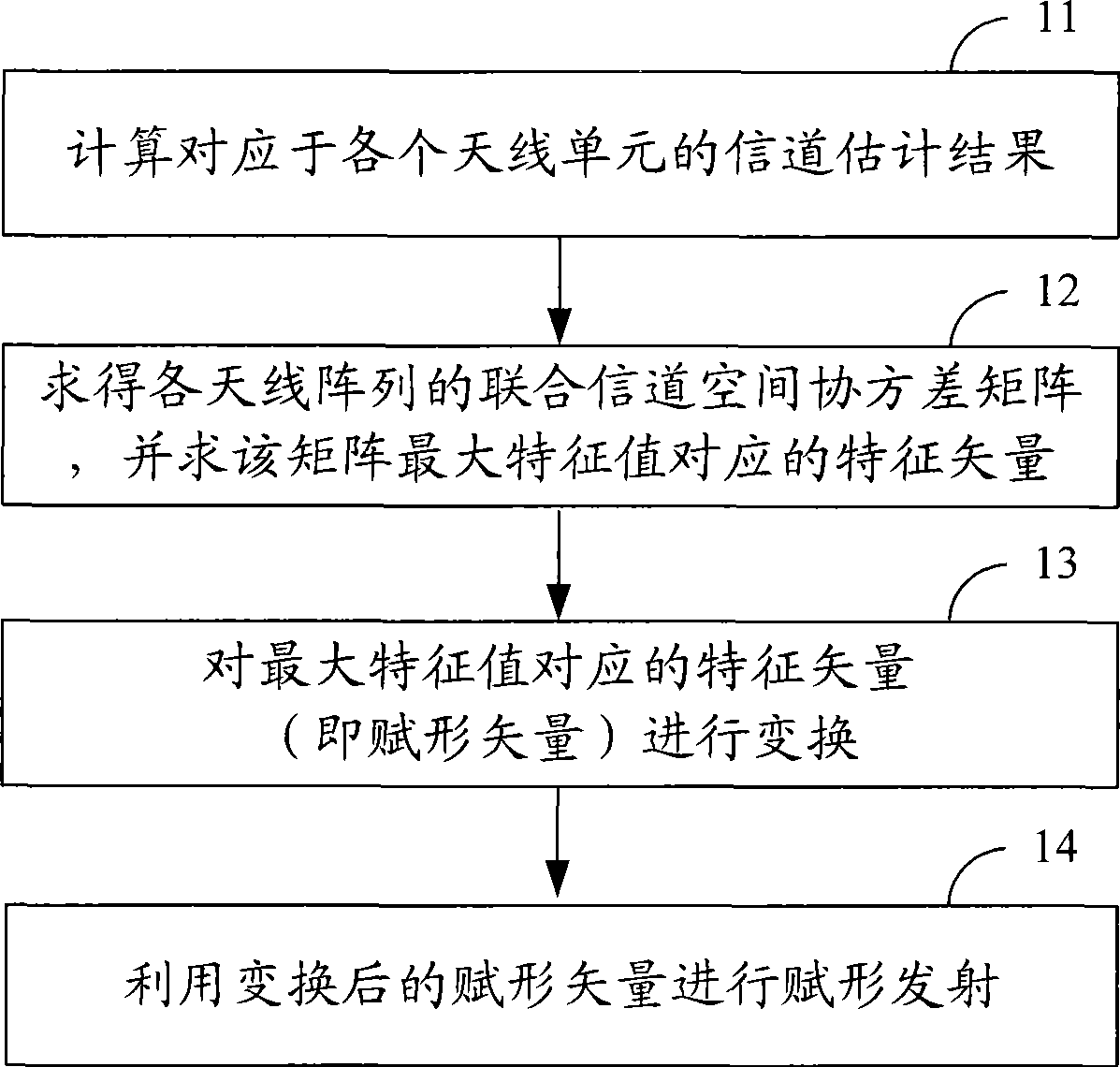
[0063] The first embodiment provided by the present invention is a beamforming method. Embodiment 1 is mainly based on the traditional eigenbeamforming algorithm, and solves the problem that each antenna (array) is caused by the asymmetry of the uplink and downlink channels in a multi-array antenna system. The problem of shape gain loss caused by unbalanced transmit power and limited power. Specific steps such as image 3 Shown:

[0064] Step 11: Calculate and obtain the channel estimation results of each antenna unit in the multi-array antenna system h ka n , ka = 1 . . . K a n , n=1...N.

[0065] Let the channel impulse response experienced by each antenna receive the signal from the transmitter to the receiver as:

[0066] h ka n ...


PUM


Abstract

Disclosed is a wave beam figuration method and apparatus, in order to solve that the existing wave beam figuration method is unable to implement the performance optimization in a multiple-array system, because of independences between arrays. The method comprises: calculating and obtaining channel estimation results hka, ka=1...Ka, n=1...N of each aerial in the multiple-array aerial system, wherein, N represents array total, N>1, Ka is the aerial unit total in the n array; calculating the combined channel space covariance matrix R of each aerial array based on the hka; calculating the characteristic vector corresponding to the maximum characteristic value of R; performing the transformation only with amplitude variation for the webb; performing the figuration transmission by using the figuration vector transformed by the webb, because of the relationship between aerial arrays, the combined wave beam figuration processing can be performed for each aerial array to enable the performance of the wave beam figuration in the multiple-array system to be optimized obviously.

Description

technical field [0001] The invention belongs to the technical field of communication, and in particular relates to a beam forming method and device. Background technique [0002] With the development of mobile communication technology, in order to improve system capacity, array antennas have been used in many systems. But at the same time, with the development of society, while enjoying the convenience brought by mobile communication, people pay more and more attention to the environment and their own health, and the electromagnetic environment has gradually become a sensitive issue that people pay attention to. In order to obtain sufficient gain, traditional array antennas often require 6-8 antennas to be arranged at a certain distance, which is much larger than the original single antenna. From an engineering point of view, the traditional array antenna is Large size also brings higher requirements to the construction. [0003] In order to solve the above problems, array...

Claims


Application Information

Patent Timeline
IPC IPC(8): H04B7/06H01Q3/26H04B7/005
CPCH04B7/0689H04B7/0848H04B7/0469H01Q3/26H04B7/043H04W52/42H04B7/10H04B7/0617H04B7/0413
Inventor 蔡月民任世岩孙长果康绍莉吴柯维徐红艳
Owner DATANG MOBILE COMM EQUIP CO LTD
Why Eureka
Try Eureka