LED driving circuit and secondary side controller thereof

A light-emitting diode and secondary-side control technology, which is applied to semiconductor devices of light-emitting elements, circuit layout, lamp circuit layout, etc., can solve problems affecting the accuracy of dimming control, increase, and increase the cost of light-emitting diode drive circuits, etc., to achieve Avoid excessive voltage stress or inaccurate dimming control, cost simplification, and reduce electromagnetic interference

Inactive Publication Date: 2009-07-22
NIKO SEMICON
View PDF0 Cites 62 Cited by
  • Summary
  • Abstract
  • Description
  • Claims
  • Application Information

AI Technical Summary

Problems solved by technology

Although the above problems can be solved by adding a voltage ramp control circuit, this not only increases the cost of the LED drive circuit, b

Method used


Image

  • LED driving circuit and secondary side controller thereof
  • LED driving circuit and secondary side controller thereof
  • LED driving circuit and secondary side controller thereof

Examples


Embodiment Construction

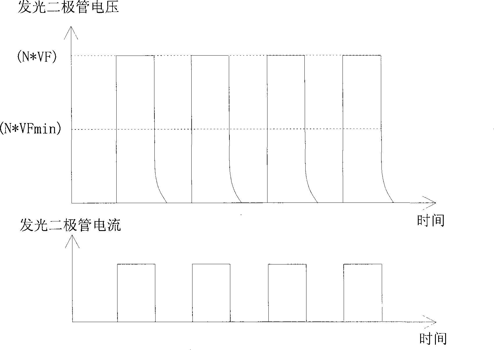
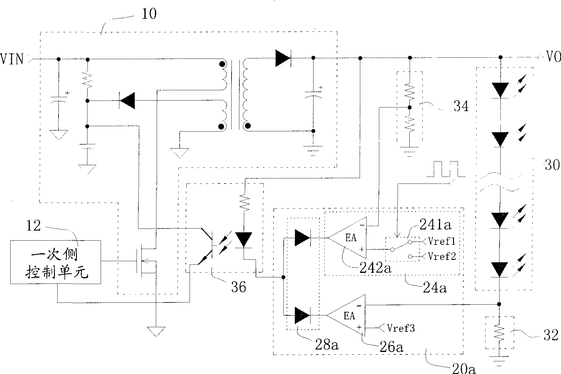
[0031]The feature of the present invention is that in the dimming control process, the output voltage of the LED driving circuit is controlled at a first driving voltage or a second driving voltage. When the output voltage is at the first driving voltage, the light-emitting diode module is under current feedback control, so it is in a stable light-emitting state; and when the output voltage is at the second driving voltage, it is under voltage feedback control, so the output voltage is approximately equal to the light-emitting diode module The critical voltage of the LED module (but greater than zero volts) makes the LED module hardly emit light, preferably slightly lower than the critical voltage of the LED module to ensure that the LED module does not emit light. In this way, during the dimming process, the voltage change applied to the LED module is smaller than the existing voltage change, so that the problems of the LED being subjected to excessive voltage or inaccurate di...


PUM


Abstract

A light emitting diode driving circuit of the invention and a secondary side controller control the output voltage to a first driving voltage or a second driving voltage. When the output voltage is in the first driving voltage, the light emitting diode module can be in a stable light emitting state. When the output voltage is in the second driving voltage, the output voltage is approximately in the threshold voltage (larger than zero voltage) of light emitting diode module so that the light emitting diode module hardly radiates. Thus the variation of voltage applied to the light emitting diode module is less than the present voltage variation in light modulation process, thereby avoiding the problem of overlarge voltage stress or inaccurate light modulation control of light emitting diodein prior art.

Description

technical field [0001] The present invention relates to a light-emitting diode driving circuit with dimming function and its secondary side controller, especially to a light-emitting diode driving voltage that can be controlled between a first driving voltage and a second driving voltage during the dimming process. LED driver circuit and its secondary side controller. Background technique [0002] Such as figure 1 Shown is the existing step-down (Buck) light-emitting diode drive circuit. When the transistor switch Q2 is turned on (TURN ON), the power supply V4 provides current to flow through the transistor switch Q2 to charge and store the inductor L1 and the capacitor C4 and at the same time provide energy to the LEDs D2 and D5 to make them emit light. When the transistor switch Q2 is turned off (TURN OFF), the inductor L1 and the capacitor C4 release energy to make the light emitting diodes D2 and D5 continue to emit light. The current flowing through the LEDs D2 and D...

Claims


Application Information

Patent Timeline
IPC IPC(8): H05B37/02H05B37/00F21V23/00F21Y101/02F21Y115/10
Inventor 冷中明
Owner NIKO SEMICON
Why Eureka
Try Eureka