
Sliding type double-cohesion step-by-step driven bottle blowing machine

A step-driven, sliding technology, applied in the field of blow molding machines, can solve the problems of easy stretching and deformation use cost, many rotating connection points, easy to produce wear, etc. quick effect

Inactive Publication Date: 2009-07-29
温振平
View PDF0 Cites 0 Cited by
  • Summary
  • Abstract
  • Description
  • Claims
  • Application Information

AI Technical Summary

Problems solved by technology

[0003] The purpose of the present invention is, one is to overcome the shortcomings of the existing bottle blowing machine, such as unstable transmission, complex structure, easy stretching deformation and high cost of use, and the other is to overcome the many mechanical rotation connection points of the existing mold locking mechanism, which is easy to produce The third is to overcome the shortcomings of the existing single-cling driving structure that is easy to cause displacement or even sliding, and provide a sliding double-cling step-driven blow molding machine with stable transmission, convenient maintenance and low cost of use.

Method used


Image

  • Sliding type double-cohesion step-by-step driven bottle blowing machine
  • Sliding type double-cohesion step-by-step driven bottle blowing machine
  • Sliding type double-cohesion step-by-step driven bottle blowing machine

Examples


specific Embodiment 1

[0029] Figure 1 to Figure 8 Constitute the specific embodiment 1 of the present invention.

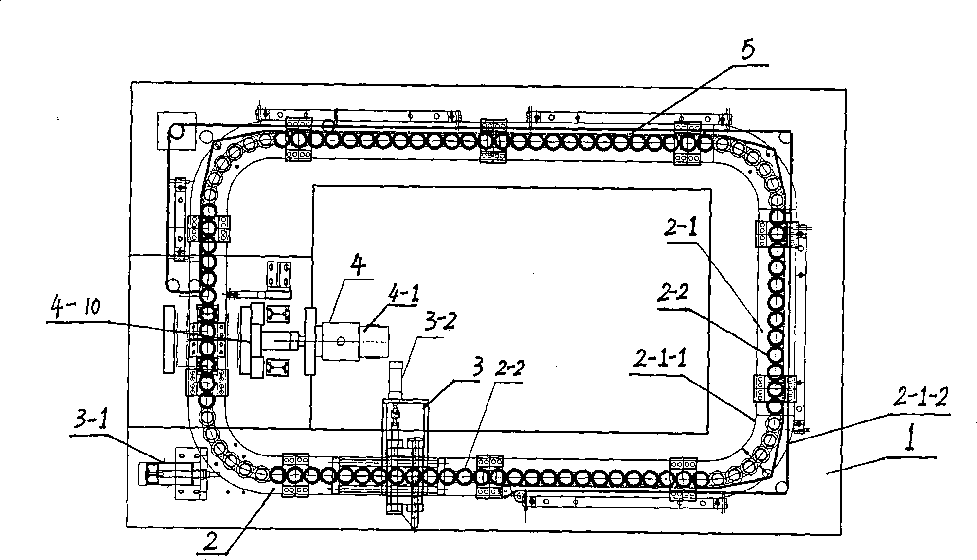
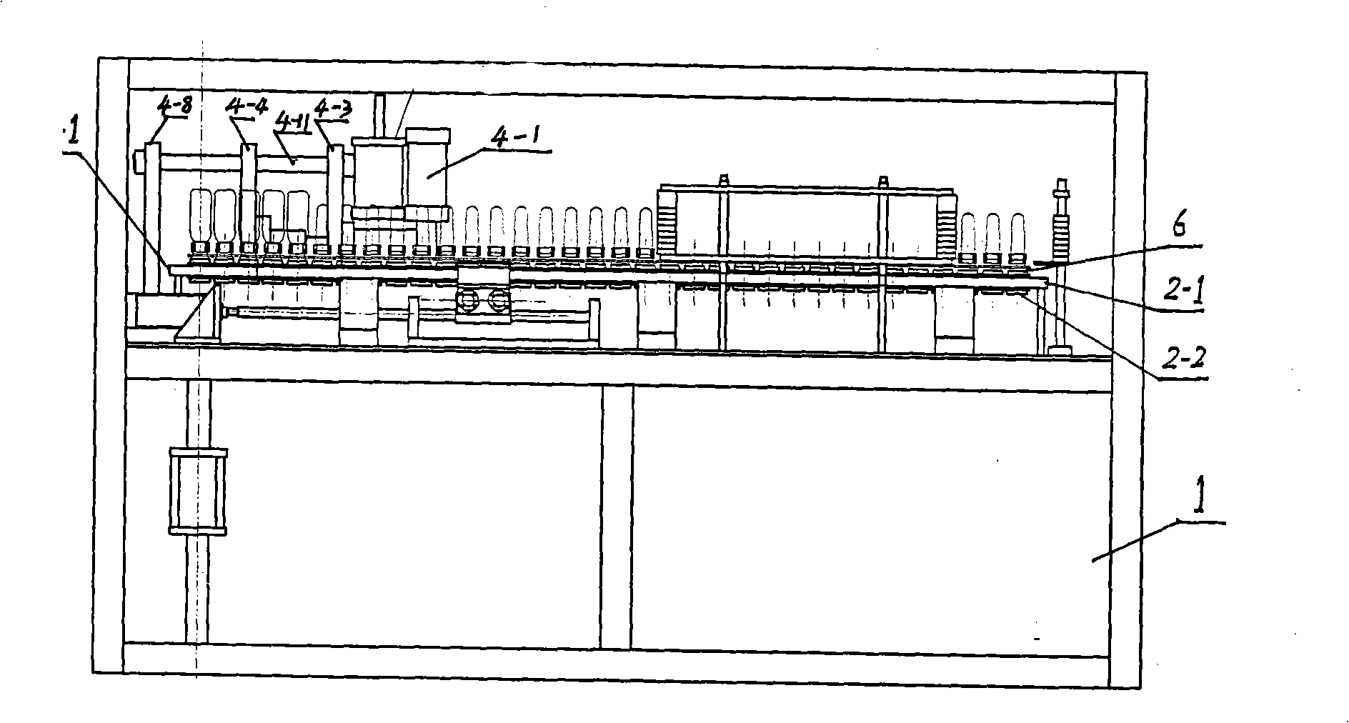
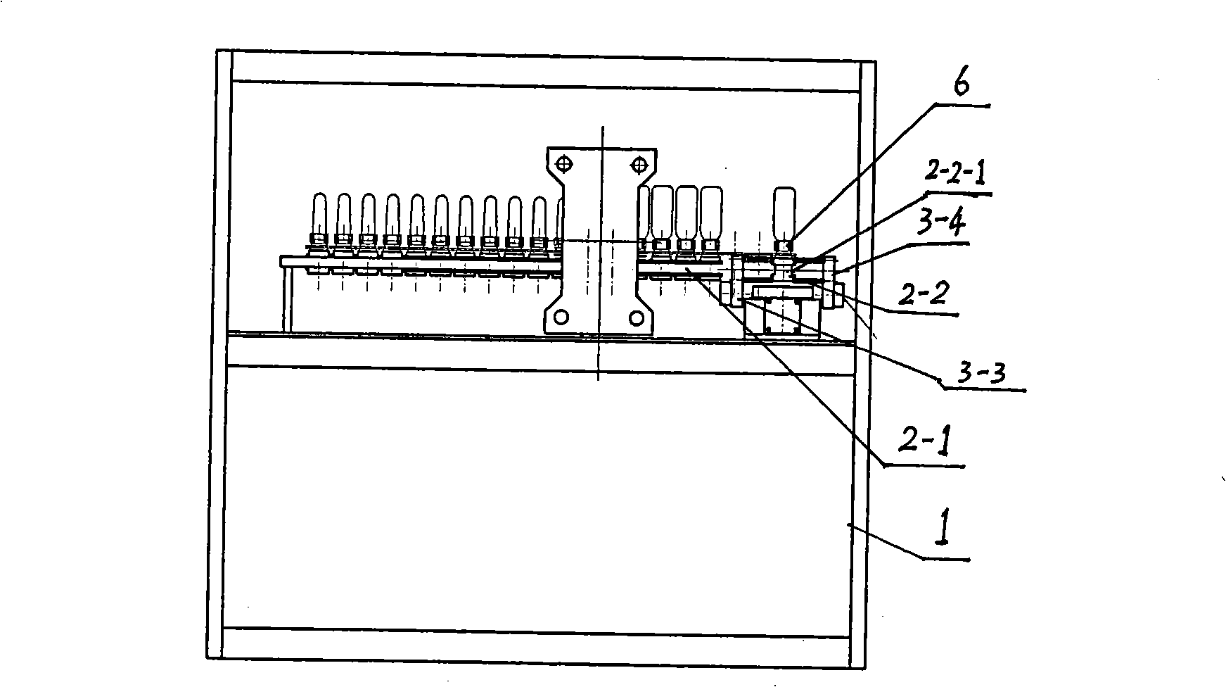
[0030] refer to Figure 1 to Figure 8 , the present embodiment includes a frame 1, a preform holder conveying device 2, a driving device 3, a clamping device 4 and a heating system 5; Constituted with the slider 2-2, the ring slide rail 2-1 includes the inner slide rail 2-1-1 and the outer slide rail 2-1-2, and the slider 2-2 is set on the inner slide rail 2-1 and the outer slide rail Between the rails 2-2, the slide block 2-2 is provided with a preform seat or an interface connected with the preform seat; the slide block 2-2 is slidably connected with the ring slide rail 2-1 and can -1 Inner progressive sliding or stepping sliding; the driving device 3 is a double-embracing stepping pneumatic driving structure, including a stepping pneumatic driving mechanism and a double-embracing grasping mechanism, and the stepping pneumatic mechanism includes a stepping cylinder 3-1 and The po...

specific Embodiment 2

[0039] The feature of this embodiment is that the slider 2-2 can be provided with a preform holder, and also can be provided with an interface connected with the preform holder, through which the slider 2-2 can be connected with the preform holder. The slider 2-2 can be in the shape of a cylinder or a cylinder, and can also be in the shape of a square or a rib, and the groove 2-2-1 on the outer surface of the slider 2-2 is an annular groove. All the other are with specific embodiment 1.

specific Embodiment 3

[0040] The characteristics of this embodiment are: in the driving device 3, one, three, four, five, eight or more than ten arc-shaped concave positions can be respectively placed on the claw 3-3 and the claw 3-4 as required, each One or more preform seats can be picked up by double-holding at the same time. To achieve the purpose of convenience, flexibility and production efficiency. All the other are with specific embodiment 1.

[0041] In the present invention, the cylinder in the driving device 3 can include a stepping cylinder positioning cylinder, using compressed air (0.6-0.8Mpa) as a power source, and driving two claws to close in the middle after one of the air inlets of the positioning cylinder enters, Hold the heating seat tightly; step into one of the air inlets of the cylinder and push the two claws to hold the heating seat tightly and step forward, two stations at a time. The two claws are separated after the second air intake of the positioning cylinder, and th...


PUM


Abstract

The invention relates to a sliding type double-cohesion stepping and driving bottle blowing machine, which comprises a machine frame (1), a bottle preform seat transporting device (2), a driving device (3), a mould locking device (4) and a heating system (5). The machine is characterized in that the bottle preform seat transporting device (2) has a sliding type transporting structure and consists of an annular slide rail (2-1) and a slide block (2-2); the driving device (3) has a double-cohesion type stepping and pneumatic driving structure and comprises a stepping and pneumatic driving mechanism and a double-cohesion clutching mechanism; the stepping and pneumatic driving mechanism comprises a stepping cylinder (3-1) and a positioning cylinder (3-2); the double-cohesion clutching mechanism consists of opposite claws (3-3) and claws (3-2); the mould locking device has a gas-liquid interacting structure and comprises a gas-liquid pressure cylinder (4-1) and a mould locking mechanism (4-10) ; and the gas-liquid pressure cylinder (4-1) is connected with the mould locking mechanism (4-10) through a shaft coupler. The machine has the advantages of high accuracy for transporting workpieces, low noise, stable bottle blowing, simple whole structure, small volume, convenient use and maintenance, and low cost.

Description

technical field [0001] The invention relates to a bottle blowing machine, in particular to a sliding double-clinging step-driven bottle blowing machine, which is widely applicable to blowing PP plastic bottles or PET plastic bottles of various specifications. It belongs to the technical field of equipment for blowing plastic containers from preforms. Background technique [0002] The equipment that blows plastic containers from preforms is commonly known as blow molding machine. Most of the blow molding machines in the prior art use an endless chain to drive the movement of the preform seat in its preform seat conveying device, and the preform seat is sent to each station by the rotation of the chain to carry out the corresponding blowing process. This kind of conveying mechanism driven by a chain has the following disadvantages: (1) the transmission is not stable, easy to shake, and the accuracy of the workpiece positioning is poor; (2) the structure is complicated, the ma...

Claims


Application Information

Patent Timeline
Patent Type & Authority Applications(China)
IPC IPC(8): B29C49/28B29C49/56B29C49/42B29L22/00
Inventor 温振平
Owner 温振平
Learn More