Floor board support member and floor board structure

A technology of supporting parts and supporting components, which is applied in the field of floor supporting parts, can solve the problems of higher height of floor supporting parts and larger interference range of mass bodies, etc., and achieve the effect of narrowing the interference range and good partition performance

Inactive Publication Date: 2009-07-29
BRIDGESTONE CORP
View PDF1 Cites 7 Cited by
  • Summary
  • Abstract
  • Description
  • Claims
  • Application Information

AI Technical Summary

Problems solved by technology

[0003] According to the floor structure described in Japanese Patent Laid-Open No. 2007-040093, although the vibration from the floor can be effectively attenuated, when the floor structure described in Japanese Patent Laid-Open No. 2007-04

Method used


Image

  • Floor board support member and floor board structure
  • Floor board support member and floor board structure
  • Floor board support member and floor board structure

Examples


Embodiment Construction

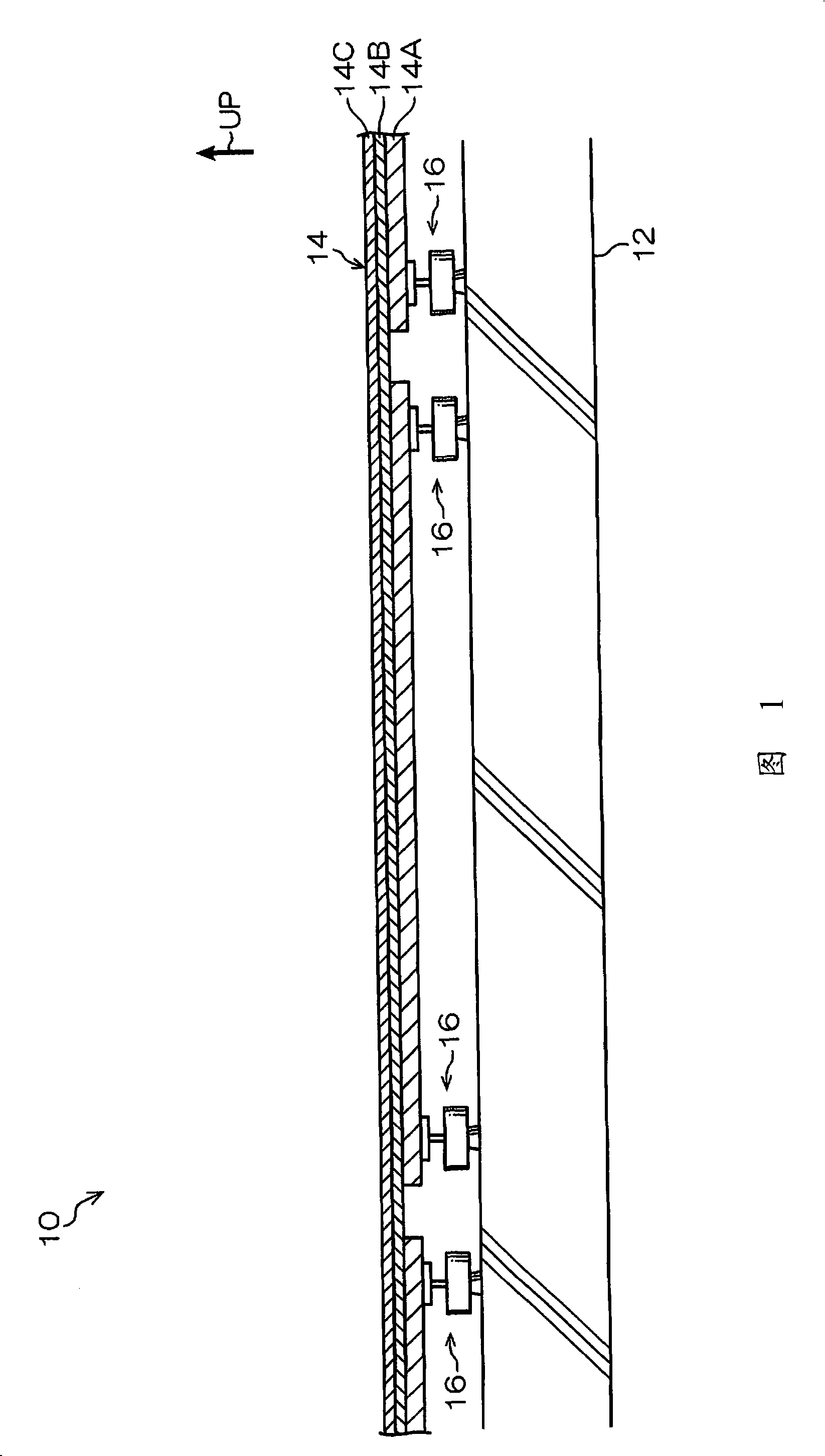
[0024] Hereinafter, embodiments of the floor support and the floor structure to which the floor support of the present invention are applied will be described with reference to the drawings. Arrow UP in the figure shows the upward direction of the floor structure.

[0025] The floor structure 10 shown in FIG. 1 is a structure mainly used for double-layer floors (dry soundproof double-layer floors) of multi-storey houses, and is used to reduce floor impact sounds (walking sounds, falling objects) generated on the upper floor and transmitted to the lower floor. sound, the sound of a child jumping, etc.).

[0026] Floor construction and structure of floor supports

[0027] As shown in FIG. 1 , the floor structure 10 is made in such a state that a plurality of floor support members 16 arranged at predetermined intervals are interposed between a concrete floor slab 12 as a floor main body and an upper floor member 14. The floor support 16 is interposed to form a space between t...


PUM


Abstract

The present invention provides a floor support member and floor construction. A mass body (40) shows a cylinder shape having a dent (42) in a central part of the lower surface (40A) under a setup status. The dent (42) is a cylinder shape with a coaxial line with the central axis of the mass body (40). Under the setup status, a buffering base frame (26) is arranged in the dent (42), and the lower surface (40A) of the mass body (40) is configured at a position of a side part of the dent (42) for coating a buffer rubber (18).

Description

technical field [0001] The present invention relates to a floor construction in which a double floor is made by means of support elements, and a floor support for supporting the floor elements of a double floor. Background technique [0002] In the floor structure, in order to improve the performance of blocking floor impact sound, there is sometimes a double floor structure in which a floor is provided on a floor base at a predetermined height via a support member. In such a double-floor structure, for example, Japanese Patent Application Laid-Open No. 2007-040093 discloses a technology for damping vibrations from the floor using an elastic body and a mass body. [0003] According to the floor structure described in Japanese Patent Laid-Open No. 2007-040093, although the vibration from the floor can be effectively attenuated, when the floor structure described in Japanese Patent Laid-Open No. 2007-040093 is adopted, the figure 2 In the configuration shown, the height of th...

Claims


Application Information

Patent Timeline
IPC IPC(8): E04F15/18E04F15/20
Inventor 阿久津悟稻叶健司塚田将
Owner BRIDGESTONE CORP
Why Eureka
Try Eureka