A chamber of a peristaltic pump for tire pressure adjustment

A tire and memory technology, applied in the field of shape memory cavity, can solve the problems that cannot be basically corrected, cannot be manufactured, and the components of a single cavity are difficult to combine with each other, and achieve the effect of cheap technical modification and easy removal

Inactive Publication Date: 2009-07-29
哥达发展公司
View PDF0 Cites 26 Cited by
  • Summary
  • Abstract
  • Description
  • Claims
  • Application Information

AI Technical Summary

Problems solved by technology

Another disadvantage is that the mutual integration of the individual cavity components is very difficult, or not yet solved; making it impossible to carry out basic corrections in the tire cavity shape manufacturing method, especially on the production machines
Another disadvantage is that it is not possible to manufacture a basic completely unique chamber assembly for every tire and its pressure

Method used


Image

  • A chamber of a peristaltic pump for tire pressure adjustment
  • A chamber of a peristaltic pump for tire pressure adjustment
  • A chamber of a peristaltic pump for tire pressure adjustment

Examples


Embodiment 1

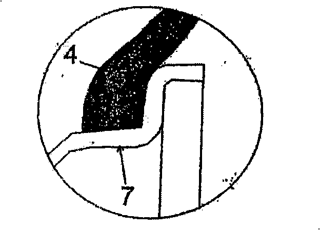
[0046] The shape memory cavity 1 for adjusting the pressure inside the tire is a part of the tire or is arranged near the outer wall of the tire. One end of the cavity is connected to the inner cavity of the tire, and the other end is connected to the outside. Its shape is a curved hollow pipe, and its outer wall The part consists of a pair of surfaces 10 coplanar with the chamber 1 (pipe) longitudinally and at an angle α = 2 to 15°. The included angle α>0° is located on the side where these surfaces 10 intersect, and is set on the side farther from the center of the cross-section of the cavity 1 . The cavity 1 is located in the region of the tire sidewall 4 of the bead of the tire.

[0047] When manufacturing the chamber 1, a flat substrate 9, which has a protrusion and is 0.8 mm wide and 0.22 mm thick, is inserted between the layers of glue constituting the sidewall 4 of the tire before vulcanization, after which the inserted substrate 9 is taken out as a whole in the direc...

Embodiment 2

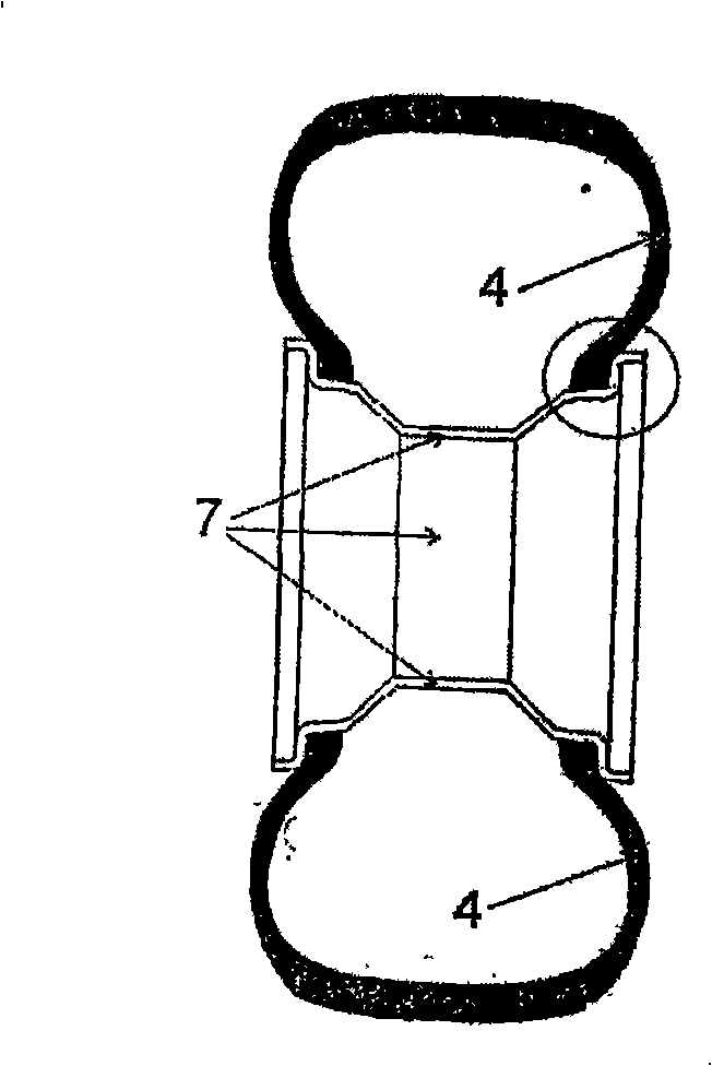
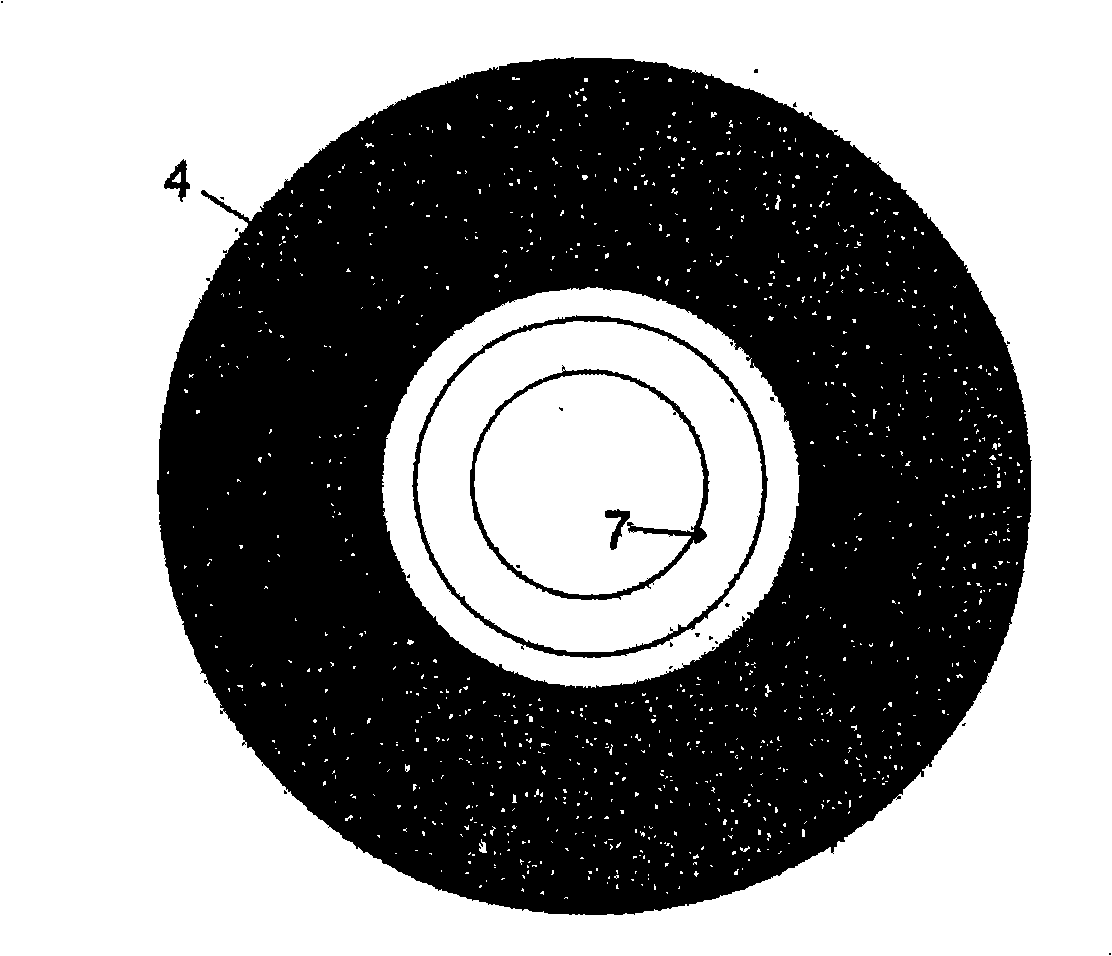
[0056] Figure 3a An auxiliary structure 6 is shown containing a cavity 1 with a three-pointed star shape in cross-section. This part of the cavity 1 is located on the outer sidewall of the tire 4 above the bead of the tire 4 and the hub 7 . The tire 4 is not shown here, the chamber 1 is shown in an unloaded state. There is an acute angle α on the surface 10 of the outer wall forming one of the corners. This acute angle will ensure the airtightness of the outer walls constituting the cavity 1 when the cavity 1 is deformed, the side walls are subject to minimal bending and tension, which will reduce the combined tension and material pressure on the outer walls of the cavity 1 . Figure 3b The cross-section through the chamber 1 is shown in the loaded state, and the outer walls of the chamber 1 are pressed against each other at the load point, so that the chamber 1 disappears and assumes a state of zero cross-sectional area. The direction of deformation caused by compression ...

Embodiment 3

[0062] The base body 9 is pressed between the outer walls of the cavity 1, and then the base body 9 is taken out, so that the cavity 1 is processed. The surfaces 10 extend themselves out of the cavity 1 with zero angle between the surfaces 10 so that the base body 9 can be easily removed when the cavity 1 is being processed.

[0063] Figure 3d The manufacture of a circular cavity 1 is shown. The part-circular base body 9 is pressed into the material of the future chamber 1 ; it extends beyond the circular cross-section of the chamber 1 and leads out of the auxiliary structure 6 . After compaction, this extension will extend the parallel surface 10 through the outer wall of the cavity 1 all the way to the outside of the auxiliary structure 6 . This creates a channel for removing the pressed-in base body 9 . The removal of the matrix 9 is done in Figure 3e shown in .

[0064] After mounting the auxiliary structure 6 and the tire 4 on the hub 7, these extended surfaces 10 ...


PUM


Abstract

A chamber (1) that works as a peristaltic pump for the pressure correction in the tire (4), which is a part of the tire (4) or of an ancillary structure (6) placed between the rim (7) and the tire bead (4) and is connected with the tire (4) internal space at one end and with the external environment at the other end. The chamber (1) is in the shape of a curved hollow channel, where at least one enclosing wall is at least partially formed by at least a pair of surfaces (10) coplanar with the longitudinal direction of the chamber (1). When the tire is mounted on the rim, the pair of surfaces (10) are pressed together thus hermetically closing the chamber (1). When the chamber (1) is closed during rotation of the wheel, the surfaces (10) can slightly slide on one another taking internal wall tensions onto themselves thus decreasing the possibility of wall damage through ripping. A method of producing the chamber (1) is also disclosed.

Description

technical field [0001] The invention relates to a shape-memory cavity for tire pressure regulation, which is a part of the tire or is arranged near the tire wall, and one end of the cavity is connected with the inner cavity of the tire, and the other end is connected with the outside. The invention also relates to such a cavity and to a method of manufacturing a tire and a wheel hub incorporating such a cavity. Background technique [0002] There are various methods of maintaining the pressure in the tire under operating conditions in the actual art. Some methods, for example, are to mount an air inlet on the tire, which is connected to an external high pressure air pump. The disadvantage of this approach is the high cost and complexity of the equipment. [0003] There are also some self-inflating tires. A typical self-inflating tire is described, for example, in pending patents CZ PV 2002-1364 and CZ PV 2001-4451. The air intake chamber is located on or near the outer w...

Claims


Application Information

Patent Timeline
Patent Type & Authority Applications(China)
IPC IPC(8): B60C23/00B60C15/024
CPCB60C23/12B60C15/06B60C23/123B60C23/135
Inventor 法兰提赛克·赫拉巴尔
Owner 哥达发展公司
Why Eureka
Try Eureka