
Steam condenser of vacuum plant

A technology of steam condenser and vacuum device, which is applied in the direction of evaporator/condenser, refrigerator, refrigeration components, etc., and can solve the problems of increased film heat transfer, reduced total heat transfer coefficient, and reduced heat exchange performance.

Active Publication Date: 2009-08-05
KYOWA VACUUM ENG
View PDF1 Cites 2 Cited by
  • Summary
  • Abstract
  • Description
  • Claims
  • Application Information

AI Technical Summary

Problems solved by technology

[0023] The problem to be solved by the present invention is that the total heat transfer coefficient of the refrigerant in the above-mentioned refrigerant pipe 26 and the heat transfer medium liquid outside the refrigerant pipe 26 is reduced, and the heat exchange performance is reduced. The heat transfer of the nucleate boiling of the refrigerant inside the tube and the heat transfer of the film of the heat transfer medium liquid outside the tube are greatly increased, and the method of promoting heat transfer

Method used


Image

  • Steam condenser of vacuum plant
  • Steam condenser of vacuum plant
  • Steam condenser of vacuum plant

Examples


Embodiment

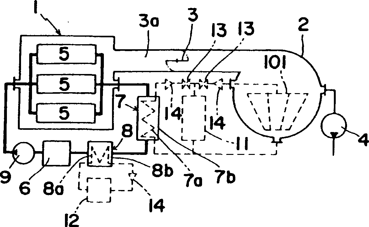
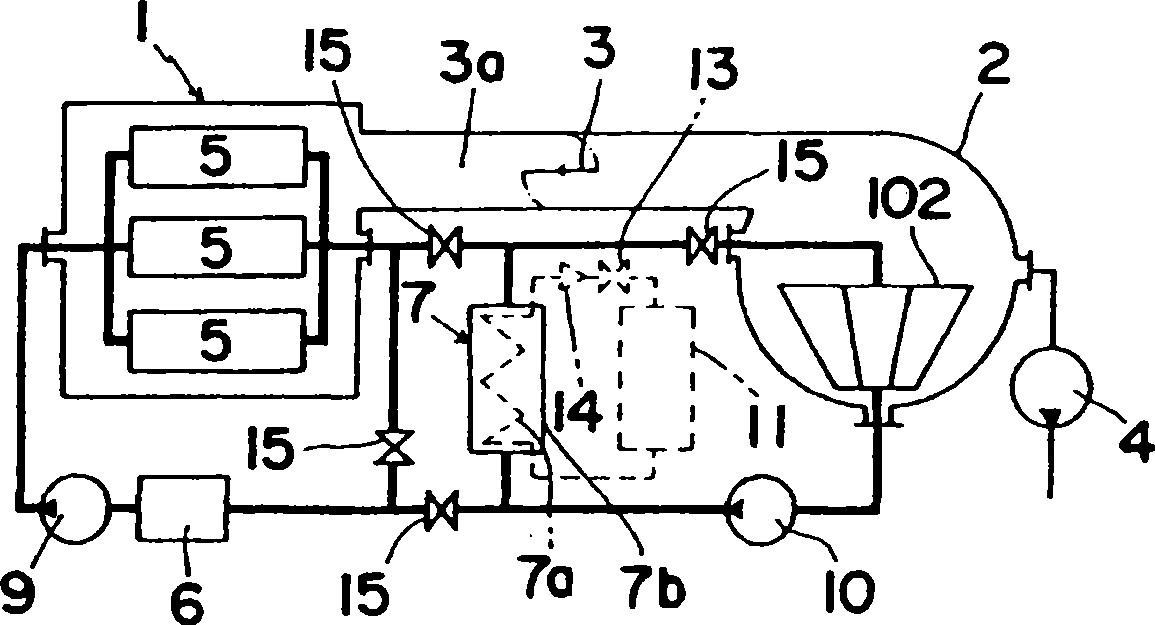
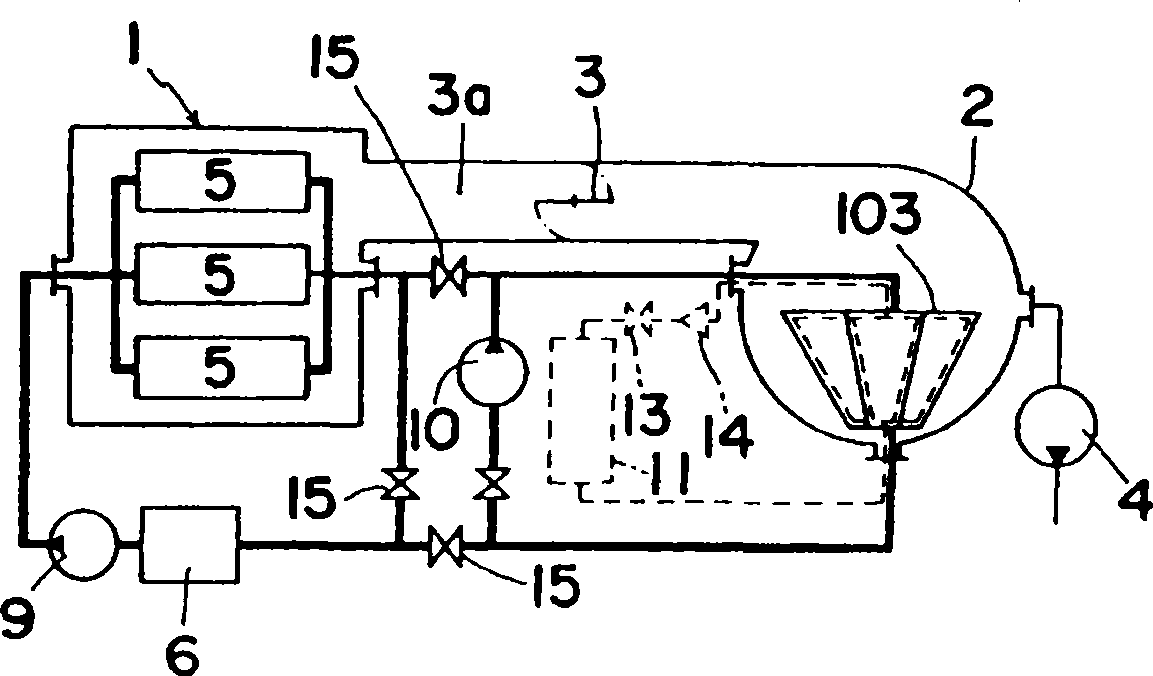
[0059] The embodiments are described in detail below according to the accompanying drawings. In addition, as for the reference numerals in the drawings, the same reference numerals are used for the same components as those in the conventional proposal.

[0060] Figure 9 It is a longitudinal sectional view of a steam condensing plate a constituting a part of the steam condenser (collector) 103 provided in the vacuum apparatus implementing the prior invention. Plate, symbol w represents the passage formed inside the steam condenser plate a, symbol B represents the heat transfer medium liquid circulating inside the passage w, and reference numeral 26 represents the refrigerant pipe installed through the inside of the passage w, symbol R represents the refrigerant circulating in the refrigerant tube 26 . In addition, the refrigerant tube 26 is deformed into an elliptical tube 16, and the inner peripheral surface thereof has a concavo-convex portion y provided with a plurality o...


PUM


Abstract

The invention relates to a steam condenser of a vacuum device. Compared with a steam condenser of a vacuum drying device, the steam condenser of a vacuum device can enhance the heat transfer performance and reduce the loss of the transmission temperature difference loss of a refrigerant and the vacuum steam of a condensing surface. A circular refrigerant evaporation tube inside the steam condenser of a vacuum drying device is changed from a smooth tube into a circular tube with an inner surface groove and then processed into a flat elliptical tube through deformation, one flat horizontal surface or two flat horizontal surfaces of a pair of flat horizontal surfaces is / are tightly attached to the inner wall surface of a channel of heat transfer medium fluid and is / are arranged in the channel to increase the tight attachment area of the inner wall surface of the channel of the heat transfer medium fluid inside a steam condensation plate and the elliptical refrigerant evaporation tube, and rods which can equidistantly generates turbulences are arranged along the elliptical refrigerant evaporation tube in the channel of the heat transfer medium fluid to confuse parallel flows of the outer surface of the elliptical refrigerant evaporation tube, thereby the heat transfer of convection films of the heat transfer medium fluid is promoted.

Description

technical field [0001] The present invention relates to the improvement of steam condensers of vacuum devices, especially the steam condensers of vacuum devices proposed as Japanese Patent No. 1177616 and Japanese Patent No. 3644845 previously developed by the applicant. Background technique [0002] The steam condenser (collector) of the vacuum device is assembled and widely used in the following way: in order to condense and collect the steam of water and other solvents evaporated from the object to be treated in the vacuum chamber on the low-temperature cooling surface, Thus, the vacuum pressure of the vacuum chamber is maintained at a desired value, and its main part is constituted by vacuum devices such as a vacuum freezing device, a vacuum drying device, a vacuum concentrator, a vacuum distillation machine, a vacuum cooler, and a solvent removal device. [0003] The collector (steam condenser) of the vacuum device supplies the cold heat to condense the vacuum steam fro...

Claims


Application Information

Patent Timeline
IPC IPC(8): F25B39/04
Inventor 砂间良二泽田宽如
Owner KYOWA VACUUM ENG
Learn More