
Electric lever type leakage preventing socket

A leakage protection and socket technology, applied in multiple unbalanced current/voltage switches, circuits, electrical components, etc., can solve the problems of slow breaking speed, difficult tripping, and inability to protect personal safety, etc., to improve the breaking speed. , the effect of protecting safety, high sensitivity and reliability

Active Publication Date: 2009-08-05
ZHEJIANG CHINT BUILDING ELECTRICS
View PDF0 Cites 9 Cited by
  • Summary
  • Abstract
  • Description
  • Claims
  • Application Information

AI Technical Summary

Problems solved by technology

However, the tripping mechanisms of various types of leakage protection sockets currently used are electronic or electromagnetic, and they all have disadvantages such as difficulty in tripping after hooking up, slow breaking speed, slow response, and low sensitivity, which cannot meet the needs of people's protection. The need for personal safety and electrical safety
For example, when the human body touches the charged body, the tripping speed of the leakage protection socket should be as fast as possible, but the tripping time of the leakage protection socket in the prior art is about 100ms
In addition, its leakage action current is about 30mA, exceeding the absolute safety current of the human body by 10mA
When the human body touches the charged body, when the leakage current exceeds 10mA, the person can no longer take the initiative to leave the charged body, but the leakage current value of 30mA (nominal value) for the tripping of the leakage protection socket has not yet been reached, and the leakage protection socket cannot trip.
It can be seen that the leakage protector with a nominal leakage current of 30mA and a tripping speed of 100ms is a leakage protection socket that can only protect electrical appliances but not personal safety.

Method used


Image

  • Electric lever type leakage preventing socket
  • Electric lever type leakage preventing socket
  • Electric lever type leakage preventing socket

Examples


Embodiment Construction

[0012] Referring to the accompanying drawings, the present invention will now be described in detail.

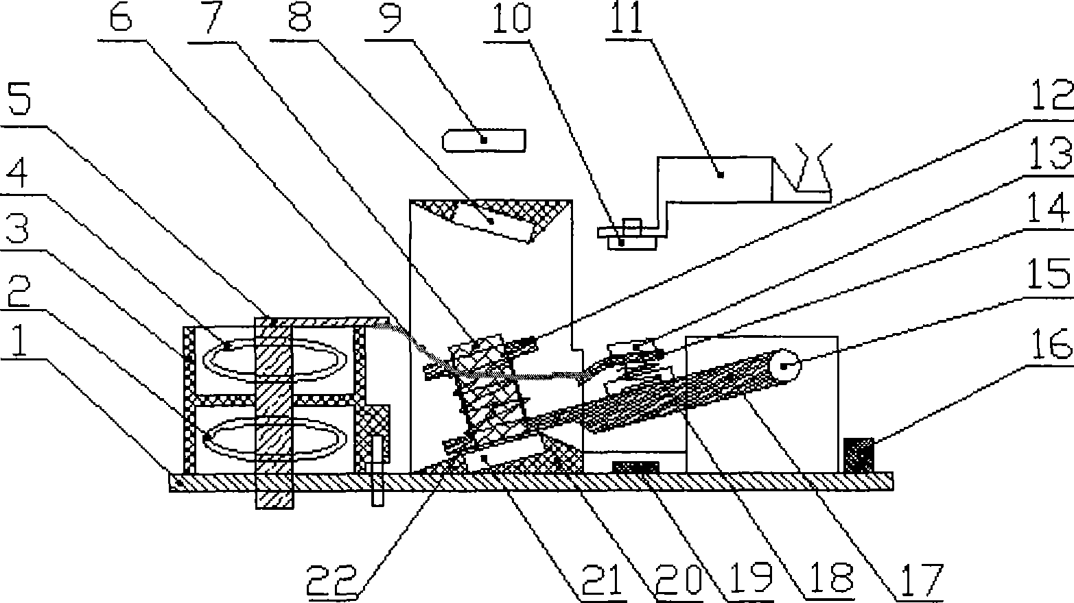
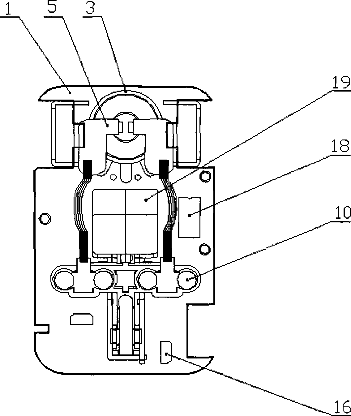
[0013] refer to figure 1 , which shows a schematic structural view of the leakage protection socket according to the present invention. The earth leakage protection socket comprises a circuit board 1 on which a transformer assembly 3, a tripping coil assembly 20, a control circuit (including a thyristor 16, a control chip 19 and other required electronic components (not shown)) are mainly installed. . The transformer assembly includes zero sequence transformer 4 (L1) and neutral transformer 2 (L2). Two conductive strips 5 of the live line L of the power supply and the neutral line N pass through the middle of the transformer assembly 3 . Copper special flexible wire 6 is spot-welded on the conductive sheet 5, and is connected with the movable contact sheet 14, and the movable contact sheet 14 is riveted with a movable contact 13, and is equipped with a contact spring 18. ...


PUM


Abstract

The invention provides a leakage protection socket, which comprises a transformer component, a trip coil component and a control circuit. The transformer component is used for detecting the current leakage in the alternating current circuit; the trip coil component comprises two fixed permanent magnets and an electromagnet which performs the reciprocating motion between the two permanent magnets; the electromagnet is provided with a lever component which can connect or disconnect the alternating current power supply along with the reciprocating motion of the electromagnet; when the socket is powered on, the control circuit controls the electromagnet of the trip coil component to be attached to one of two permanent magnets, so as to drive the lever component to connect the alternating current power supply; and when the transformer component detects that current leakage occurs in the alternating current circuit, the electromagnet is controlled to be attached to the other permanent magnet, so as to drive the lever component to disconnect the alternating current power supply. The invention has the advantages of small leakage action current, high-speed disconnection, and high reliability and sensitivity, thereby more effectively protecting the security of the personal and the electrical equipment.

Description

technical field [0001] The invention relates to a protective socket for safe use of electricity, in particular to an electric leakage protection socket capable of ensuring the safety of users and electric appliances. Background technique [0002] With the development of electronic technology, various leakage protectors have been widely used to provide safety protection for people's electricity consumption and electrical equipment. However, the tripping mechanisms of various types of leakage protection sockets currently used are electronic or electromagnetic, and they all have disadvantages such as difficulty in tripping after hooking up, slow breaking speed, slow response, and low sensitivity, which cannot meet the needs of people's protection. Personal safety and electrical safety needs. For example, when the human body touches the charged body, the tripping speed of the leakage protection socket should be as fast as possible, but the tripping time of the leakage protectio...

Claims


Application Information

Patent Timeline
IPC IPC(8): H01R13/713H01H83/14
Inventor 祝振卿陈玉
Owner ZHEJIANG CHINT BUILDING ELECTRICS
Learn More