Output current compensation circuit of LED driving circuit

A technology of LED driving and output current, applied in the direction of electric lamp circuit layout, electric light source, adjusting electric variables, etc., can solve the problems of affecting the life of LED load, affecting the stability of light emission, poor current stability characteristics of LED driving circuit, etc. Effects of Flow Properties

Active Publication Date: 2009-08-05
HANGZHOU SILAN MICROELECTRONICS
View PDF0 Cites 31 Cited by
  • Summary
  • Abstract
  • Description
  • Claims
  • Application Information

AI Technical Summary

Problems solved by technology

[0008] The disadvantage of the LED drive circuit in the above-mentioned hysteresis control mode is: due to the influence of internal logic delay, comparator rise delay and fall delay, when the LED drive circuit drives the LED load, its input voltage Vin or / and the external LED output voltage When Vout changes, the average current Iavg of the LED load will change, making the steady current characteristics of the LED drive circuit poor
use figure 1 The LED drive circuit in the hysteresis control mode shown generally has a 5% to 15% change in output current when the input voltage changes from 6 to 30V. On the one hand, it makes the current of the LED load difficult to control and affects the stability of light emission; on the other hand On the one hand, when the input voltage Vin and output voltage Vout change, the output current of the LED drive circuit will increase, and when it exceeds the rated current of the LED load, it will seriously affect the life of the LED load

Method used


Image

  • Output current compensation circuit of LED driving circuit
  • Output current compensation circuit of LED driving circuit
  • Output current compensation circuit of LED driving circuit

Examples


Embodiment Construction

[0055] The content of the present invention will be further described below in conjunction with the accompanying drawings.

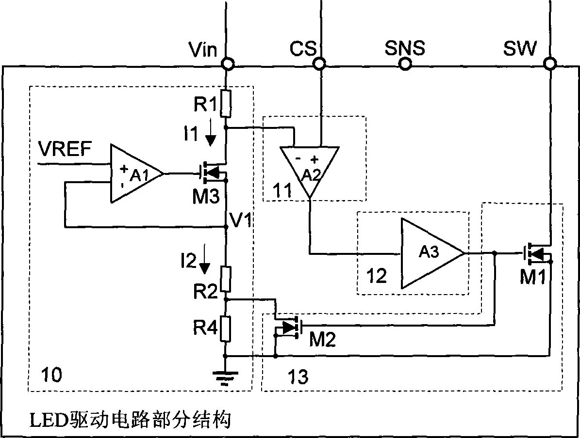
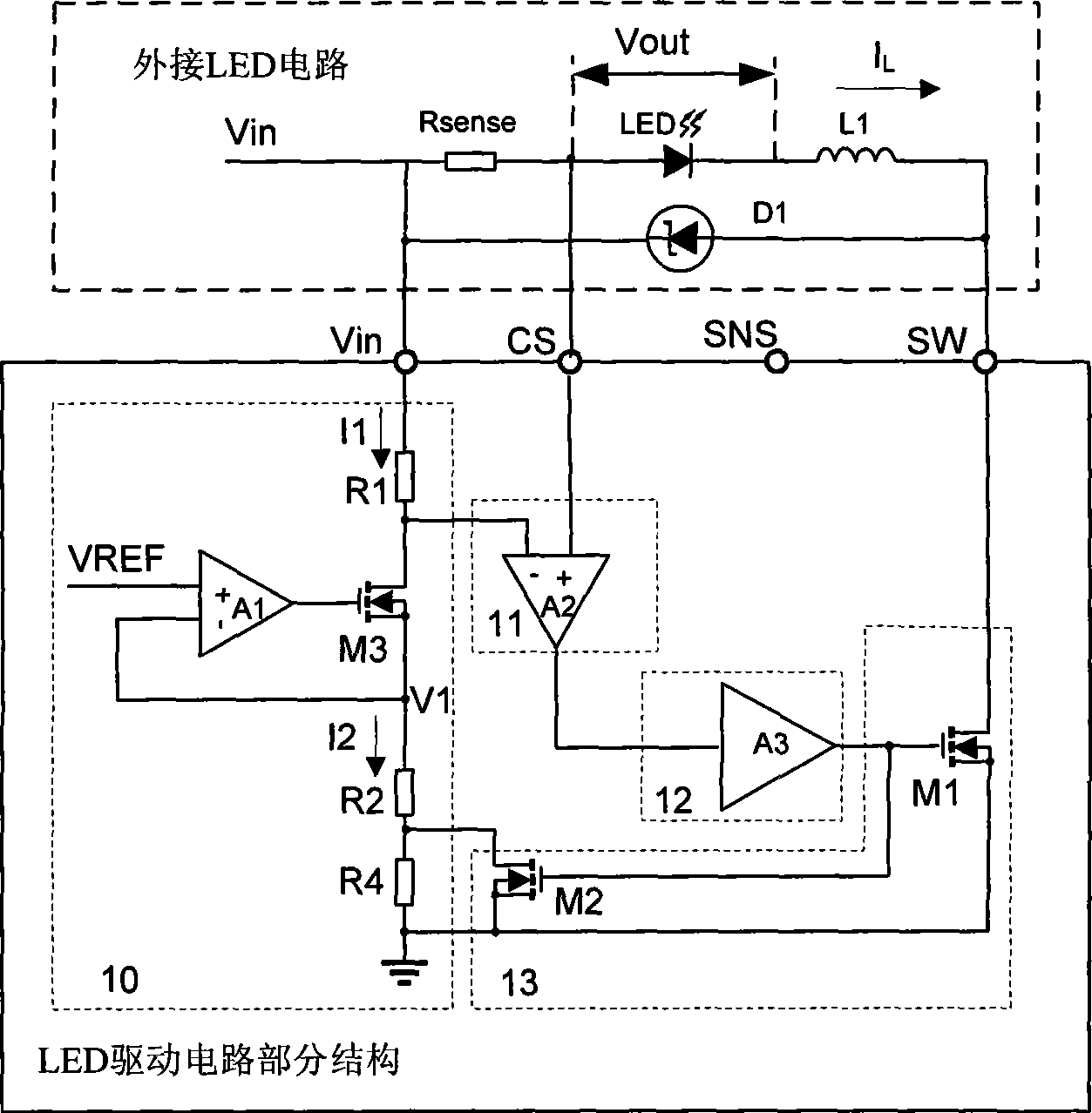
[0056] as attached figure 1 When the LED driving circuit (partial circuit structure) shown is driving the LED load, the LED driving circuit is connected with an external LED circuit to form an LED driving circuit system. The system structure is as follows figure 2 As shown: the external LED circuit includes a serial connection of sampling resistor Rsense, LED load, inductor and Schottky diode D1; the sampling resistor Rsense is connected across the Vin port and CS port of the LED drive circuit; the LED The positive pole of the load is connected to the CS port of the LED driving circuit, the negative pole is connected to one end of the inductor, and the other end of the inductor is connected to the SW port of the LED driving circuit; the Schottky diode D1 is connected across the Vin port of the LED driving circuit With the SW port, its PN junction is fo...


PUM


Abstract

The invention discloses an output current compensating circuit of an LED driving circuit, which comprises a threshold value setting module, a comparing module, a driving module, a switch module and a compensating module. The threshold value setting module is used for setting threshold voltage; the comparing module is used for comparing the threshold voltage set by the threshold value setting module and the level of sampling voltage of the LED driving circuit; the output voltage of the comparing module realizes the signal enhancement by the driving module and controls the starting and shutoff of the switch module, thereby adjusting the threshold voltage set by the threshold value setting module; and the compensating module is used for adjusting the threshold voltage of the LED driving circuit and compensating the effect on the LED output current, caused by the change of external input voltage Vin and / or external LED output voltage.

Description

technical field [0001] The invention relates to the field of LED drive circuits, in particular to the output current compensation technology of the LED drive circuit in hysteresis control mode. Background technique [0002] At present, LED drive circuits with hysteresis control mode are widely used in LED drive circuits, especially high-power LED drive circuits. The control loop is simple, no slope compensation and frequency compensation are required, and the required external components are few, which is convenient for customers to use. [0003] figure 1 It is a partial structural diagram of the LED drive circuit of the currently adopted hysteresis control mode, including a threshold setting module (10), a comparison module (11), a driving module (12) and a switch module (13), wherein: [0004] The threshold setting module (10) includes a voltage follower module composed of an operational amplifier A1 and an NMOS transistor M3 and several resistors, the positive input term...

Claims


Application Information

Patent Timeline
Patent Type & Authority Applications(China)
IPC IPC(8): H05B37/02G05F1/46
Inventor 王栋谢小高吴建兴
Owner HANGZHOU SILAN MICROELECTRONICS
Why Eureka
Try Eureka