Injector for a fuel injection system

An injection system and injector technology, applied in fuel injection devices, special fuel injection devices, charging systems, etc., can solve problems such as steep characteristic curves, and achieve the effects of avoiding manufacturing costs and increasing pressure areas

Inactive Publication Date: 2009-08-05
ROBERT BOSCH GMBH
View PDF0 Cites 7 Cited by
  • Summary
  • Abstract
  • Description
  • Claims
  • Application Information

AI Technical Summary

Problems solved by technology

Therefore only a small closing force is available, which causes problems when metering small injection quantities, since the characteristic curve of this injector is very steep

Method used


Image

  • Injector for a fuel injection system
  • Injector for a fuel injection system
  • Injector for a fuel injection system

Examples


Embodiment Construction

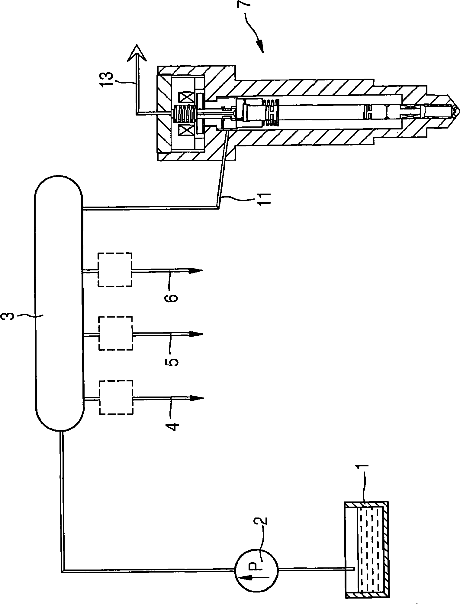
[0022] figure 1 A common rail injection system is schematically shown in . Fuel is delivered from a fuel tank 1 by means of a pump unit 2 to a high-pressure fuel accumulator 3 and is charged with high pressure. The fuel charged at high pressure is then distributed as required to the individual cylinders of the internal combustion engine to be supplied. Injection of high-pressure fuel takes place via injectors 4 , 5 , 6 and 7 . exist figure 1 Only the injector 7 is shown here for the sake of clarity.

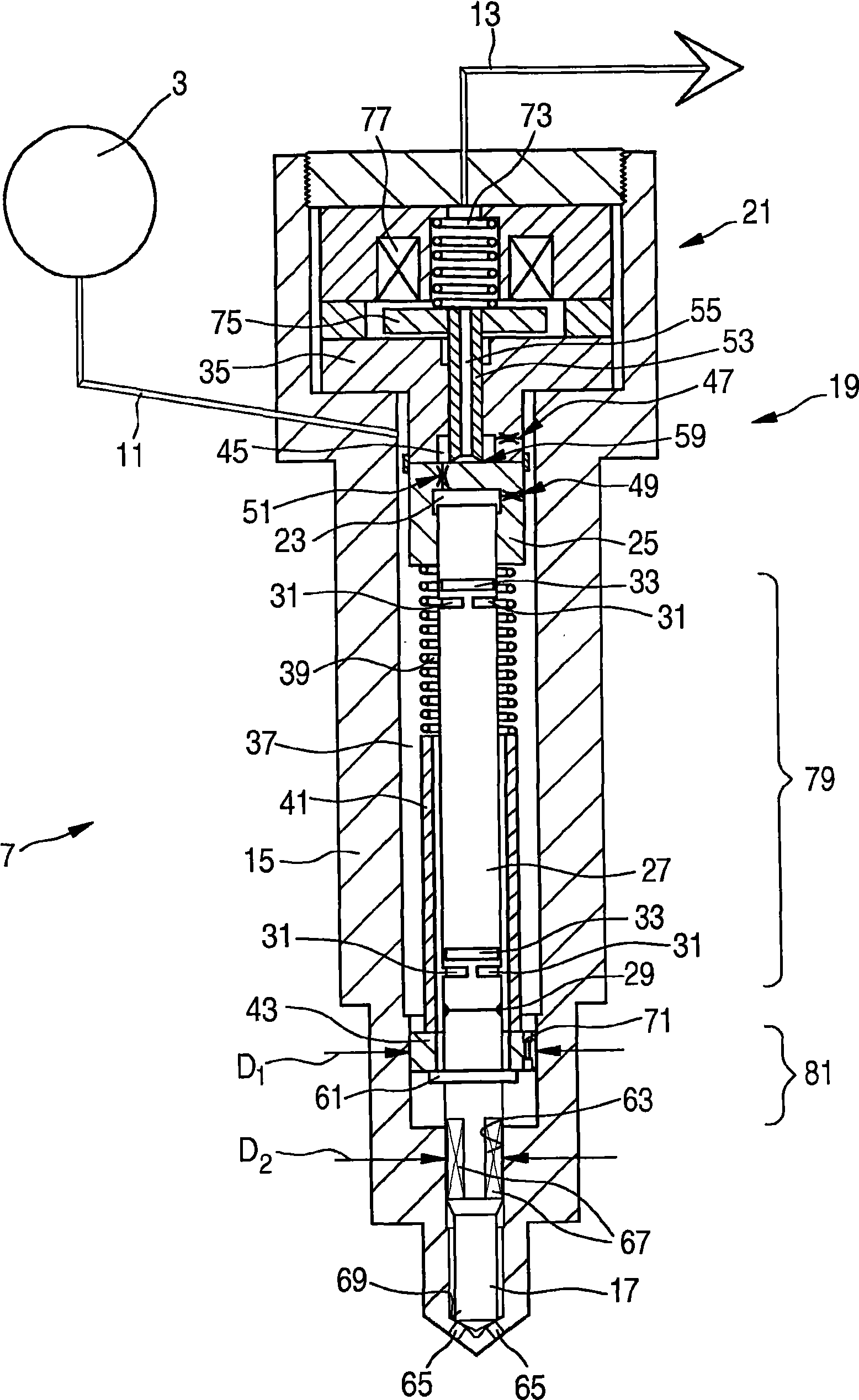
[0023] The injector 7 is connected to the common rail 3 via a high-pressure connection 11 . In addition, the injector 7 is hydraulically connected to the fuel tank 1 via an almost pressure-free fuel return line 13 . Below with the help of figure 2 with 3 The injector 7 is explained in detail.

[0024] The injector 7 includes a housing 15 in which a nozzle needle 17 is guided. A control valve 19 according to the invention and an electromagnetic actuator 21 are arranged a...


PUM


Abstract

A leak-free injector (7) is proposed, the closing force of which is increased by a closing piston (43).

Description

technical field [0001] The invention relates to an injector for an injection system of an internal combustion engine, which has a nozzle needle and a control valve, as is known, for example, from DE 10 2004 058 184.3. Background technique [0002] In order to further improve the emission values ​​of internal combustion engines, the injection pressure must be increased. In order to keep the leakage volume low in this case, injectors are used without pressure staging of the nozzle needle, so that the entire nozzle needle is surrounded by fuel at rail pressure. Only low closing forces are therefore available, which causes problems when metering small injection quantities, since the characteristic curve of such injectors is very steep. Contents of the invention [0003] The object of the present invention is to provide an injector which, despite the design of the nozzle needle without pressure stages, still provides a sufficiently high closing force. [0004] According to th...

Claims


Application Information

Patent Timeline
Patent Type & Authority Applications(China)
IPC IPC(8): F02M47/02F02M61/18F02M61/16F02M61/20
CPCF02M2200/28F02M47/027F02M63/0015F02M63/004F02M2547/003F02M61/167F02M61/205F02M63/0043F02M63/0225F02M63/0026F02M47/02F02M61/18F02M61/16F02M61/20
Inventor M·门尼肯H-C·马热尔M·布格尔
Owner ROBERT BOSCH GMBH
Why Eureka
Try Eureka