Vehicle controller

A vehicle control device, vehicle technology, applied in the direction of control devices, electrical controls, vehicle components, etc., can solve the problems of reduced response of actuators and inability to operate actuators, etc.

Inactive Publication Date: 2009-08-05
TOYOTA JIDOSHA KK
View PDF1 Cites 4 Cited by
  • Summary
  • Abstract
  • Description
  • Claims
  • Application Information

AI Technical Summary

Problems solved by technology

Insufficient supply hydraulic pressure of the hydraulic oil may lead to a failure in that the actuator cannot be operated in an appropriate manner, such as a reduction in the operational response of the actuator or a substantial inoperability.

Method used


Image

  • Vehicle controller
  • Vehicle controller
  • Vehicle controller

Examples


Embodiment Construction

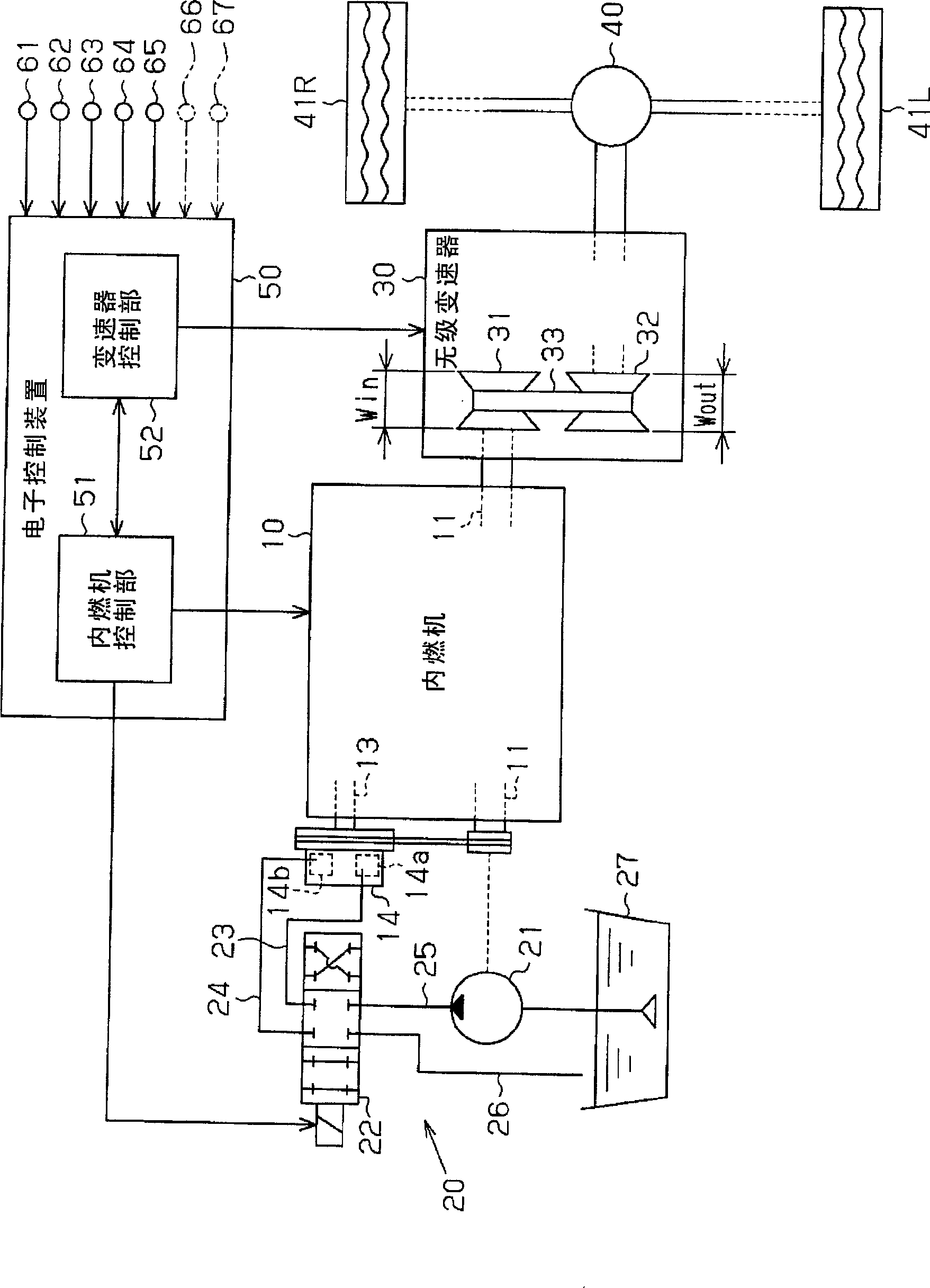
[0017] Below, refer to Figure 1 to Figure 7 An embodiment in which the present invention is embodied as a vehicle control device will be described. figure 1 It is a schematic configuration diagram showing the configuration of an internal combustion engine, a continuously variable transmission, and a vehicle on which the internal combustion engine and the continuously variable transmission are to be controlled by the vehicle control device of the present embodiment.

[0018] Such as figure 1 As shown, the end of the intake side camshaft 13 that opens and closes the intake valve (not shown) of the internal combustion engine 10 is provided with a valve timing changing device 14 that changes the valve timing of the intake valve. Similarly, a valve timing changing device 14 for changing the valve timing of the exhaust valve is provided at the end of the exhaust side camshaft 13 that opens and closes the exhaust valve. exist figure 1 Only the valve timing changing device 14 p...


PUM


Abstract

A vehicle has an engine-driven oil pump driven based on the rotation of the output shaft of an engine, a valve timing change device operating based on hydraulic pressure supplied from the oil pump, and a stepless transmission capable of continuously changing a transmission ratio. An electronic control device sets the transmission ratio of the stepless transmission according to operating conditions of the vehicle. The electronic control device changes the set transmission ratio so that, when the supply pressure of hydraulic oil supplied from the oil pump to the valve timing change device is low, the speed of the engine rises.

Description

technical field [0001] The present invention relates to a continuously variable transmission that includes an internal combustion engine-driven oil pump driven by rotation of an output shaft of the internal combustion engine, a hydraulic actuator that operates according to the pressure of hydraulic oil supplied from the oil pump, and a continuously variable transmission that can continuously change the transmission ratio vehicle control device. Background technique [0002] Conventionally, as a vehicle transmission, for example, as described in Patent Document 1, a continuously variable transmission capable of continuously (steplessly) changing a gear ratio according to a vehicle running state has been proposed. In the speed change control of such a continuously variable transmission, refer to as Figure 8 The shift diagram shown. The target rotation speed NEtrg is set based on an engine output demand value such as an accelerator opening and a vehicle speed V. FIG. Then, t...

Claims


Application Information

Patent Timeline
Patent Type & Authority Applications(China)
IPC IPC(8): F16H61/02B60K25/02F02D13/02F02D29/00F02D29/04F02D45/00F16H59/42F16H59/74F16H59/78F16H61/66F16H61/662F16H63/50
CPCF16H2061/66286F16H61/66259Y02T10/76F16H2061/66277F16H61/66272
Inventor 宫野尾裕二
Owner TOYOTA JIDOSHA KK
Why Eureka
Try Eureka