

Optical space transmission system using visible light and infrared light
A space transmission and visible light technology, applied in transmission systems, free space transmission, electromagnetic wave transmission systems, etc., can solve problems such as low-speed optical communication and difficult high-speed communication, and achieve the effect of improving communication speed
- Summary
- Abstract
- Description
- Claims
- Application Information
AI Technical Summary
Problems solved by technology
Method used
Image

Examples
no. 1 Embodiment approach
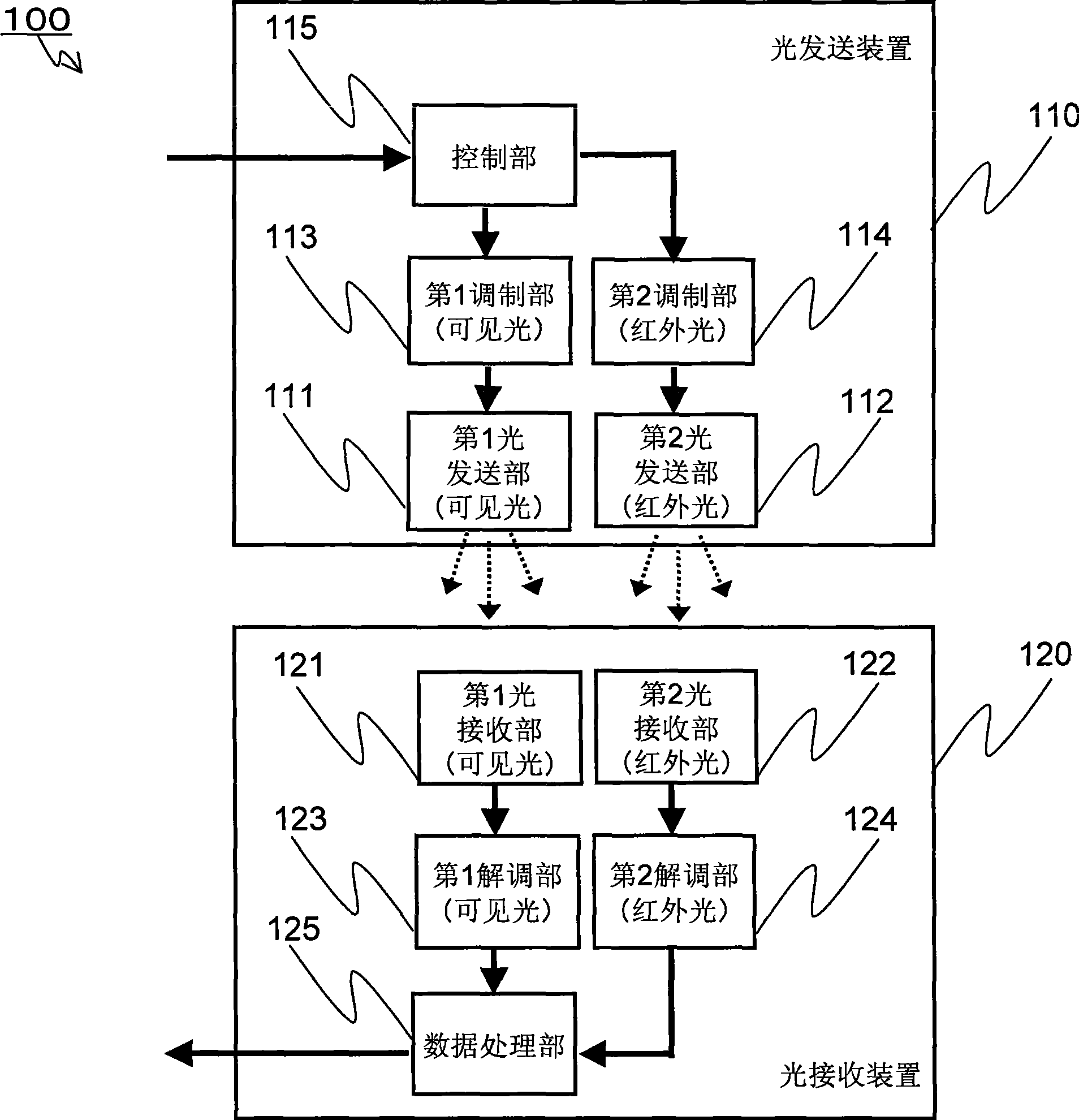
[0087] figure 1 It is a diagram showing a schematic configuration example of the optical space transmission system 100 according to the first embodiment of the present invention. Such as figure 1 As shown, the optical space transmission system 100 includes: an optical transmission device 110 and an optical receiving device 120 . The optical transmission device 110 includes a control unit 115 , a first modulation unit 113 , a second modulation unit 114 , a first optical transmission unit 111 , and a second optical transmission unit 112 . The light receiving device 120 includes a first light receiving unit 121 , a second light receiving unit 122 , a first demodulation unit 123 , a second demodulation unit 124 , and a data processing unit 125 .
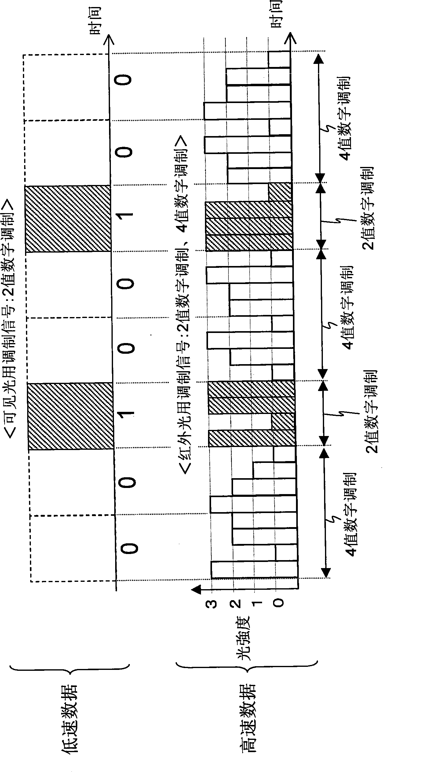
[0088] figure 2 It is a schematic diagram of the modulation signal waveform for visible light output by the first modulation unit 113 and the modulation signal waveform for infrared light output by the second modulation unit 114 . ...
no. 2 Embodiment approach
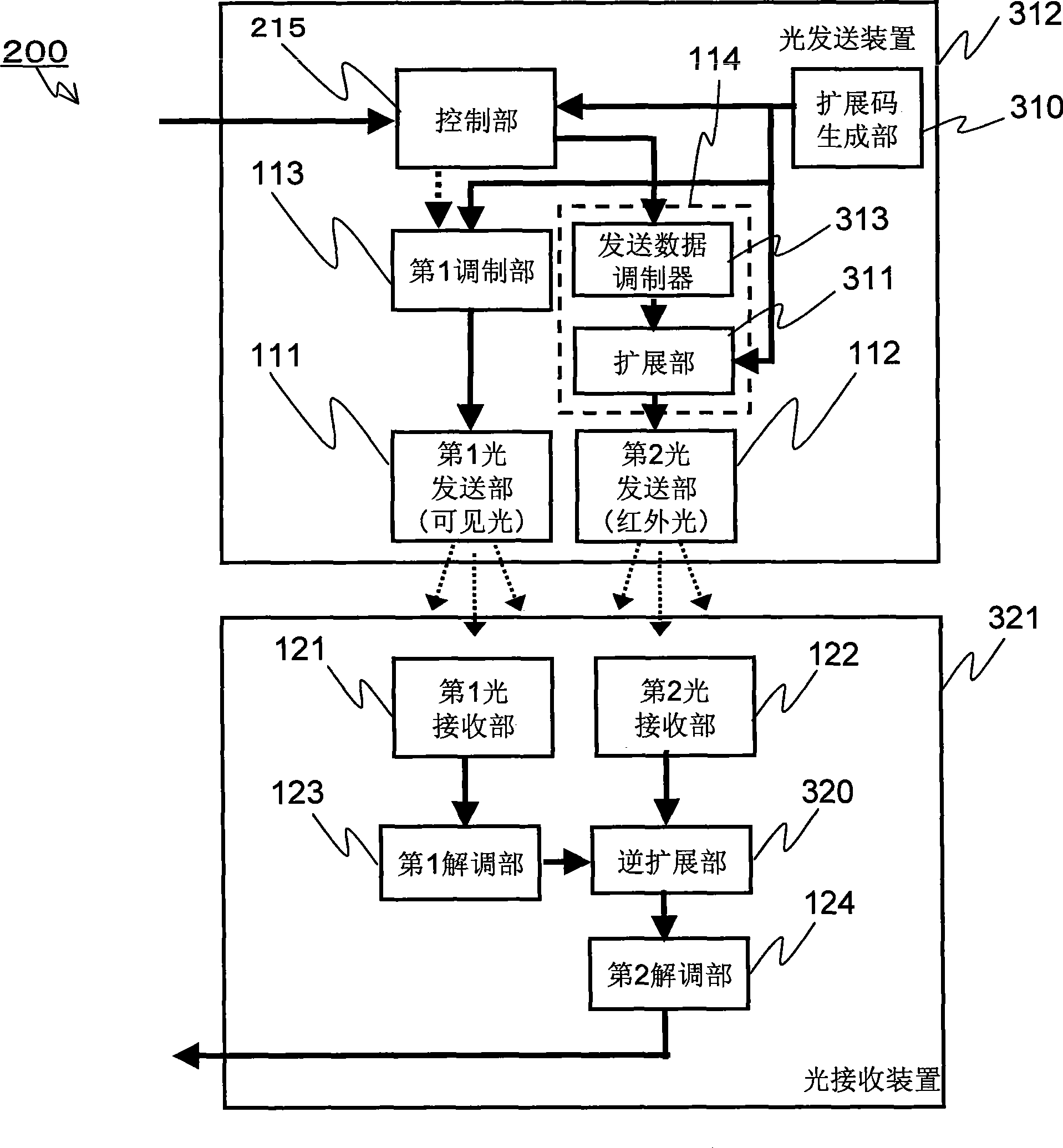
[0096] image 3 It is a diagram showing a schematic configuration example of the optical space transmission system 200 according to the second embodiment of the present invention. Such as image 3 As shown, the optical space transmission system 200 includes an optical sending device 312 and an optical receiving device 321 . The optical transmission device 312 is compared to the optical transmission device 110 (refer to figure 1 ), the control unit 115 is replaced with the control unit 215 and further includes a spreading code generation unit 310 . Furthermore, the second modulation unit 114 included in the optical transmission device 312 includes a transmission data modulator 313 and an extension unit 311 . The optical receiving device 321 further includes the despreading unit 320 and does not include the data processing unit 125 , compared to the optical receiving device 120 included in the optical space transmission system 100 . Additionally, for image 3 The optical s...
no. 3 Embodiment approach
[0102] Figure 5 It is a diagram showing a schematic configuration example of the optical space transmission system 300 according to the third embodiment of the present invention. Such as Figure 5 As shown, the optical space transmission system 300 includes an optical sending device 312 and an optical receiving device 423 . The light receiving device 423 is compared with the light receiving device 321 (refer to image 3) includes a light receiving unit 420 , a first filter unit 421 and a second filter unit 422 instead of the first light receiving unit 121 and the second light receiving unit 122 . Additionally, for Figure 5 In the optical space transmission system 300 of the present invention, the same components as those of the optical space transmission system 200 of the second embodiment are denoted by the same reference numerals, and detailed description thereof will be omitted. Refer to the following Figure 5 , the operation of the optical space transmission system...
PUM
 Abstract
Description
Claims
Application Information