Heat exchanger structure of air conditioner

A technology for heat exchangers and air conditioners, applied in refrigerators, evaporators/condensers, lighting and heating equipment, etc., can solve the problems of unsatisfactory use environment of air conditioners, reducing energy efficiency ratio of air conditioners, and reducing air volume, etc. The effect of increasing flow, reducing noise and reducing resistance

Inactive Publication Date: 2009-08-12
LG ELECTRONICS (TIANJIN) APPLIANCES CO LTD
View PDF0 Cites 19 Cited by
  • Summary
  • Abstract
  • Description
  • Claims
  • Application Information

AI Technical Summary

Problems solved by technology

This structural form of the existing air conditioner heat exchanger has some imperfections, so it has the following deficiencies: 1. Since the heat exchanger is generally arranged in front or behind the fan of the air conditioner, when the air conditioner is working, the fan High-speed rotation makes the airflow at the inlet and outlet have a strong rotational momentum, and the direction of the fins 1 of the heat exchanger arranged in front or behind the fan is perpendicular to the direction of the rotating airflow generated by the fan, which will inevitably affect the The air flow creates considerable resistance, which reduces the air volume and reduces the energy efficiency of the air conditioner, especially in window air conditioners.
2. Because the distance between the heat exchanger and the fan is very close, the direction of the airflow generated by the fan does not match the direction of the fin 1 of the heat exchanger, which will inevitably cause noise and result in an unsatisfactory operating environment for the air conditioner, so it needs to be improved

Method used


Image

  • Heat exchanger structure of air conditioner
  • Heat exchanger structure of air conditioner

Examples


Embodiment Construction

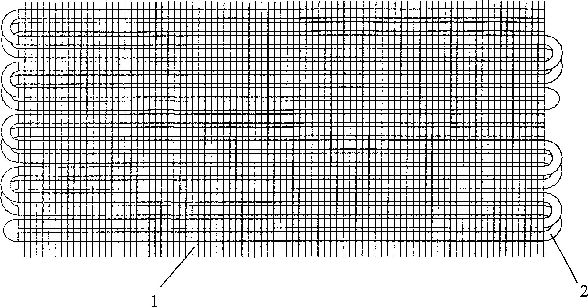
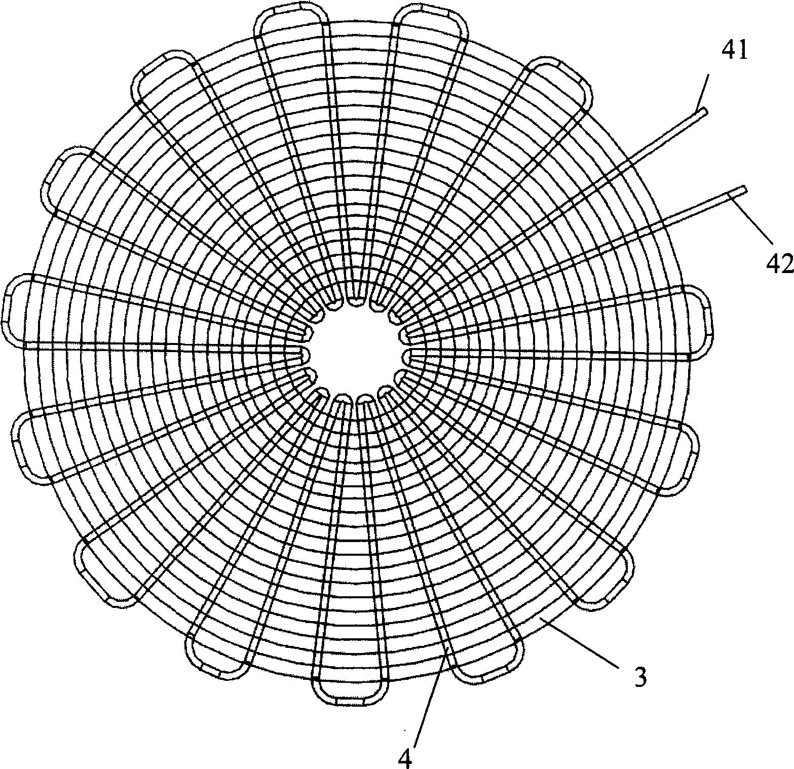
[0017] refer to figure 1 As shown, the heat exchanger structure of the air conditioner of the present invention includes a plurality of fins 3 arranged in parallel at intervals and heat exchange tubes 4 pierced in the fins 3; the improvement is that the fins 3 are annular bodies, A plurality of annular fins 3 are concentrically arranged in parallel at radial intervals; the heat exchange tubes 4 are radially arranged and penetrated in the annular fins 3 , and the ends of the heat exchange tubes are connected by U-shaped elbows.

[0018] refer to figure 1 As shown, in the heat exchanger structure of the air conditioner of the present invention, the heat exchange tube 4 is provided with the same number of inlets 41 and outlets 42; the heat exchange tube 4 is provided with one or more inlets 41 and outlets 42 .

[0019] refer to figure 1 As shown, the preparation of the air conditioner heat exchanger structure of the present invention adopts a flat annular body made of aluminum ...


PUM


Abstract

The invention provides a heat exchanger structure of an air conditioner, which comprises a plurality of fins paralelly arranged at intervals and heat exchange tubes inserted in the fins; the heat exchanger structure has improvements that the fins are annular bodies, and the plurality of annular fins are arranged concentrically, racially, parallelly and at intervals; and the heat exchange tubes are arranged and inserted into the annular fins radially, end parts of the heat exchange tubes are connected by U-shaped elbows to form a plate-shaped heat exchanger, each heat exchange tube is provided with one or more inlets and outlets, and the fins are matched with the direction of the air flow generated by the fan so as to effectively reduce air flow resistance, increase air flow rate, reduce noises and improve energy efficiency ratio of the air conditioner.

Description

technical field [0001] The present invention relates to an air conditioner, in particular to a heat exchanger provided with disc-shaped fins, the direction of which the fins are arranged to form a good match with the direction of the rotating airflow of the fan of the air conditioner, so as to increase the flow rate of the airflow and reduce the airflow resistance and noise. Air conditioner heat exchanger structure. Background technique [0002] The air conditioner is a device that cools and warms the air in the indoor space after exchanging heat between the refrigerant circulating through the compressor, condenser, expansion device, and heat exchanger, and the air passing through the heat exchanger. The structure of the air conditioner includes an outdoor unit including a compressor, a condenser, and an expansion device, and an indoor unit including a fan and a heat exchanger, and the outdoor unit and the indoor unit are connected to each other through refrigerant piping. ...

Claims


Application Information

Patent Timeline
Patent Type & Authority Applications(China)
IPC IPC(8): F25B39/00
Inventor 闫小康
Owner LG ELECTRONICS (TIANJIN) APPLIANCES CO LTD
Why Eureka
Try Eureka