
Positioning device for optoelectronic tubes on encoding disc

A technology of photoelectric tube pairing and positioning device, which is applied in the direction of measuring device, conversion sensor output, instrument, etc., can solve the problems of large workload and low efficiency, and achieve the effect of improving work efficiency and reducing cost.

Inactive Publication Date: 2009-08-12
INST OF OPTICS & ELECTRONICS - CHINESE ACAD OF SCI
View PDF0 Cites 6 Cited by
  • Summary
  • Abstract
  • Description
  • Claims
  • Application Information

AI Technical Summary

Problems solved by technology

By analogy, if four or five sets of infrared light-emitting tubes are used in the work, the workload during debugging will be very large and the efficiency will be very low

Method used


Image

  • Positioning device for optoelectronic tubes on encoding disc
  • Positioning device for optoelectronic tubes on encoding disc
  • Positioning device for optoelectronic tubes on encoding disc

Examples


Embodiment Construction

[0016] The present invention will be described in detail below in conjunction with the accompanying drawings and specific embodiments.

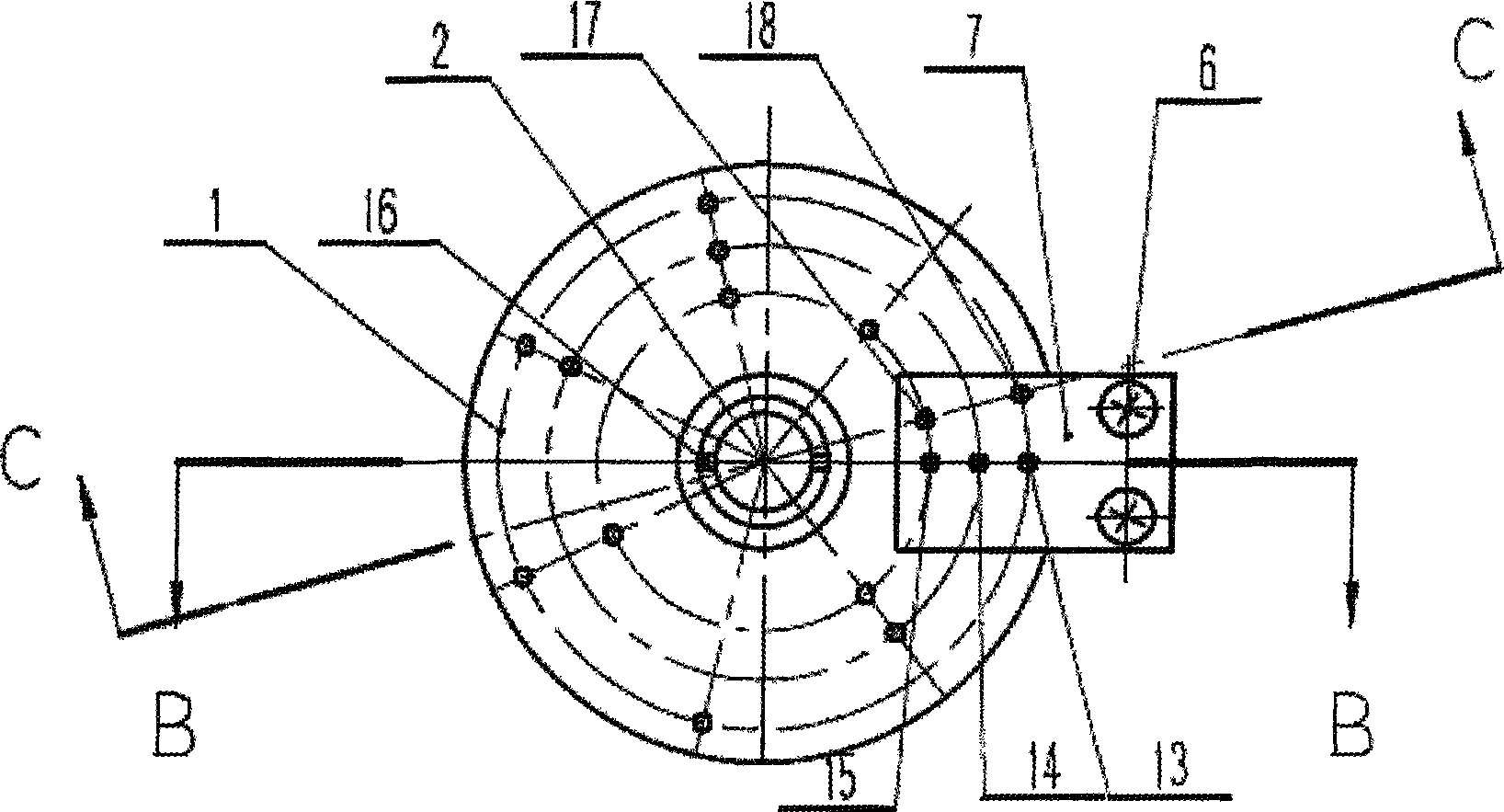
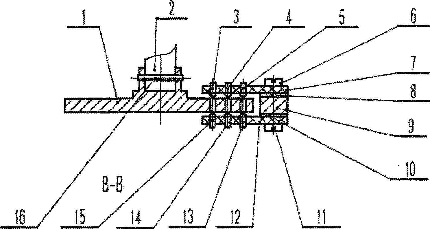
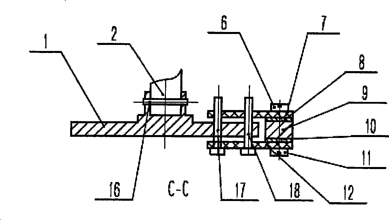
[0017] This embodiment takes the three-digit code disc 1 as an example to describe in detail. The corresponding code disc 1 is provided with 7 groups of small holes according to the three-digit binary system. The number of logarithms is 3 pairs, which is the same as the number of digits of the code disc 1; similarly, when the code disc 1 has four digits, there are 15 groups of small holes correspondingly opened on the code disc 1 according to the four-digit binary, as described in the positioning device The logarithm of the pairs of the infrared photoelectric receiving tube and the infrared photoluminescent tube is 4 pairs, which is the same as the number of digits of the code disc 1; the rest is the same.

[0018] Such as figure 1 ,Such as figure 2 ,Such as image 3 As shown, the accurate positioning device of the photoelectric tube on t...


PUM


Abstract

The invention discloses a device for positioning a photoelectric pair tube on a code disc, wherein the code disc is provided with a plurality of groups of small holes according to the binary system; two positioning holes are punched on a receiving tube circuit board and a luminotron circuit board by taking the center of the code disc as an axle center and rotating for 10 to 20 DEG relative to the infrared photoelectric pair tube; and the size and the position of the two positioning holes can be overlaid with a certain group of nonadjacent small holes on the code disc. Under the condition of debugging, two pin stops are used for fixing the receiving tube circuit board and the luminotron circuit board and the code disc together; the luminotron circuit board and the receiving tube circuit board are fixed on a supporting seat; the two pin stops are drawn out; and accurate positioning is completed. The device avoids the repeated debugging operation by an oscillograph, greatly improves the work efficiency, and meets the requirements of high efficiency and low cost of the modern scientific development.

Description

technical field [0001] The invention relates to a device for accurate positioning of photoelectric tubes on an instrument code disk. Background technique [0002] In recent years, due to the rapid development of integrated circuit technology, electronic counting and positioning systems have become more and more widely used in scientific instruments, and their integration has become higher and higher, and electronic devices have become smaller and smaller. In the electric filter dimming device, a small-power and small-volume infrared photoelectric tube that is not afraid of light interference is used to encode and position the tube. The advantage of using this infrared photoelectric tube is that it can convert the light response signal caused by stray light irradiation. Eliminate. Three groups of infrared photoelectric tubes are used in the electric filter dimming device, and each group of infrared photoelectric tubes is distributed on both sides of the code disc. When worki...

Claims


Application Information

Patent Timeline
IPC IPC(8): G01D5/347
Inventor 任绍恒李建凤
Owner INST OF OPTICS & ELECTRONICS - CHINESE ACAD OF SCI
Learn More