
Bi-stable acceleration induction micro-switch based on adhesion
A technology of acceleration sensing and micro-switching, which is applied in the direction of electric switches, coupling of optical waveguides, and components of TV systems, etc. Mis-off and other problems, to improve the conduction reliability, avoid external disturbances, and easy to assemble
- Summary
- Abstract
- Description
- Claims
- Application Information
AI Technical Summary
Problems solved by technology
Method used
Image

Examples
Embodiment 1
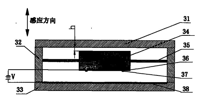
[0029] Embodiment 1, the inductive micro switch of the present invention consists of three parts: a frame body, an inductive component and an electrode plate. Wherein the frame body is composed of the left and right frames 32, the upper top cover 31 and the lower bottom cover 33 to form an airtight cavity; the sensing part is composed of a sensing mass 34 and a support beam 35, both of which are photolithographically integrated, and the support beam 36 adopts two ends. The straight beam structure is fixed on the frame 32, and the distance h between the mass block 34 and the upper top cover 31 is 1 μm. A gold film is deposited on the lower part of the mass block 34 to form a movable plate 36, and two hemispherical contacts 37 are arranged on the movable plate 36; a gold film is deposited on the inner side of the lower bottom cover 33 to form a fixed plate 38 . The gap between the movable plate 36 and the fixed plate 38 is 10 μm, and a DC voltage of 26V is passed between the tw...
Embodiment 2
[0030]Embodiment 2, the inductive micro switch of the present invention consists of three parts: a frame body, an inductive component and an electrode plate. Wherein the frame body is composed of the left and right frames 32, the upper top cover 31 and the lower bottom cover 33 to form an airtight cavity; the sensing part is composed of a sensing mass 34 and a support beam 35, both of which are photolithographically integrated, and the two ends of the support beam are The straight beam structure is fixed on the frame 32, and the distance h between the mass block 34 and the upper top cover 31 is 0.6 μm. A gold film is deposited on the lower part of the mass block 34 to form a movable plate 36, and two hemispherical contacts 37 are arranged on the movable plate 36; a gold film is deposited on the inner side of the lower bottom cover 33 to form a fixed plate 38 . The gap between the movable plate 36 and the fixed plate 38 is 10 μm, and a DC voltage of 26V is passed between the t...
Embodiment 3
[0031] Embodiment 3, the inductive micro switch of the present invention consists of three parts: a frame body, an inductive component and an electrode plate. Wherein the frame body is composed of the left and right frames 32, the upper top cover 31 and the lower bottom cover 33 to form an airtight cavity; the sensing part is composed of a sensing mass 34 and a support beam 35, both of which are photolithographically integrated, and the two ends of the support beam are The straight beam structure is fixed on the frame 32, and the distance h between the mass block 34 and the upper top cover 31 is 0.1 μm. A gold film is deposited on the lower part of the mass block 34 to form a movable plate 36, and two hemispherical contacts 37 are arranged on the movable plate 36; a gold film is deposited on the inner side of the lower bottom cover 33 to form a fixed plate 38 . The gap between the movable plate 36 and the fixed plate 38 is 10 μm, and a DC voltage of 26V is passed between the ...
PUM
 Abstract
Description
Claims
Application Information