Rotor position estimation and correction method for permanent magnet synchronous generator

A generator rotor, permanent magnet synchronous technology, applied in the direction of controlling generators, electrical components, control systems, etc., can solve the problems affecting the reliability of the system, limiting the scope of use of the system, and the accuracy of the sensor is difficult to meet the requirements, and achieves good application prospects, Strong anti-interference ability, achieve simple effect

Active Publication Date: 2009-08-12
NARI TECH CO LTD +1
0 Cites 31 Cited by

AI-Extracted Technical Summary

Problems solved by technology

However, this type of sensor has problems such as installation, cable connection, failure, etc., and affects the reliability of the system and limits the scope of use of the system. It...

Method used

The experiment has adopted position correction method 1 to correct the phase difference between the basic position signal and the actual position signal, and the estimated position signal after correction and the actual position signal waveform ar...

Abstract

The invention provides a method for estimating and correcting the position of a permanent-magnetic synchronous generator rotor. The method comprises the following steps that: by taking zero crossing points of the pole-tip phase/line voltage of a motor as boundaries, a 360-degree electrical angle of a motor rotor is divided into twelve electrical-angle intervals; by taking the relative relation between the phase/line voltage of three phase and zero as a general judgment method of a current angle interval and taking a special judgment process of the current electrical-angle interval provided as a basis, the current electrical-angle interval is judged; according to the electrical rotational speed of the generator rotor, an electrical-angle increment of the motor rotor is obtained through calculation; the sum of the increments of an angle corresponding to an initial point and the electrical angle relative to the initial point in each electrical-angle interval is a position signal of the motor rotor; by taking the quantity of the position signal as the quantity of a basic position signal, the deviation quantity of the position information of the motor rotor is estimated through specific control algorithm; and by taking the deviation quantity as the feedback quantity of a position-correcting link, the quantity of the basic position signal is compensated with an output result through the regulation of a regulator, so that an accurate position signal of the motor rotor can be obtained.

Application Domain

Electric generator control

Technology Topic

Image

  • Rotor position estimation and correction method for permanent magnet synchronous generator
  • Rotor position estimation and correction method for permanent magnet synchronous generator
  • Rotor position estimation and correction method for permanent magnet synchronous generator

Examples

  • Experimental program(1)

Example Embodiment

[0020] Hereinafter, the present invention will be further described in detail with reference to the accompanying drawings and the embodiments. However, the present invention is not limited to the examples given.
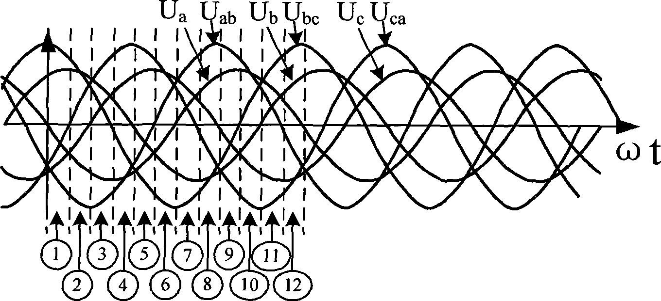
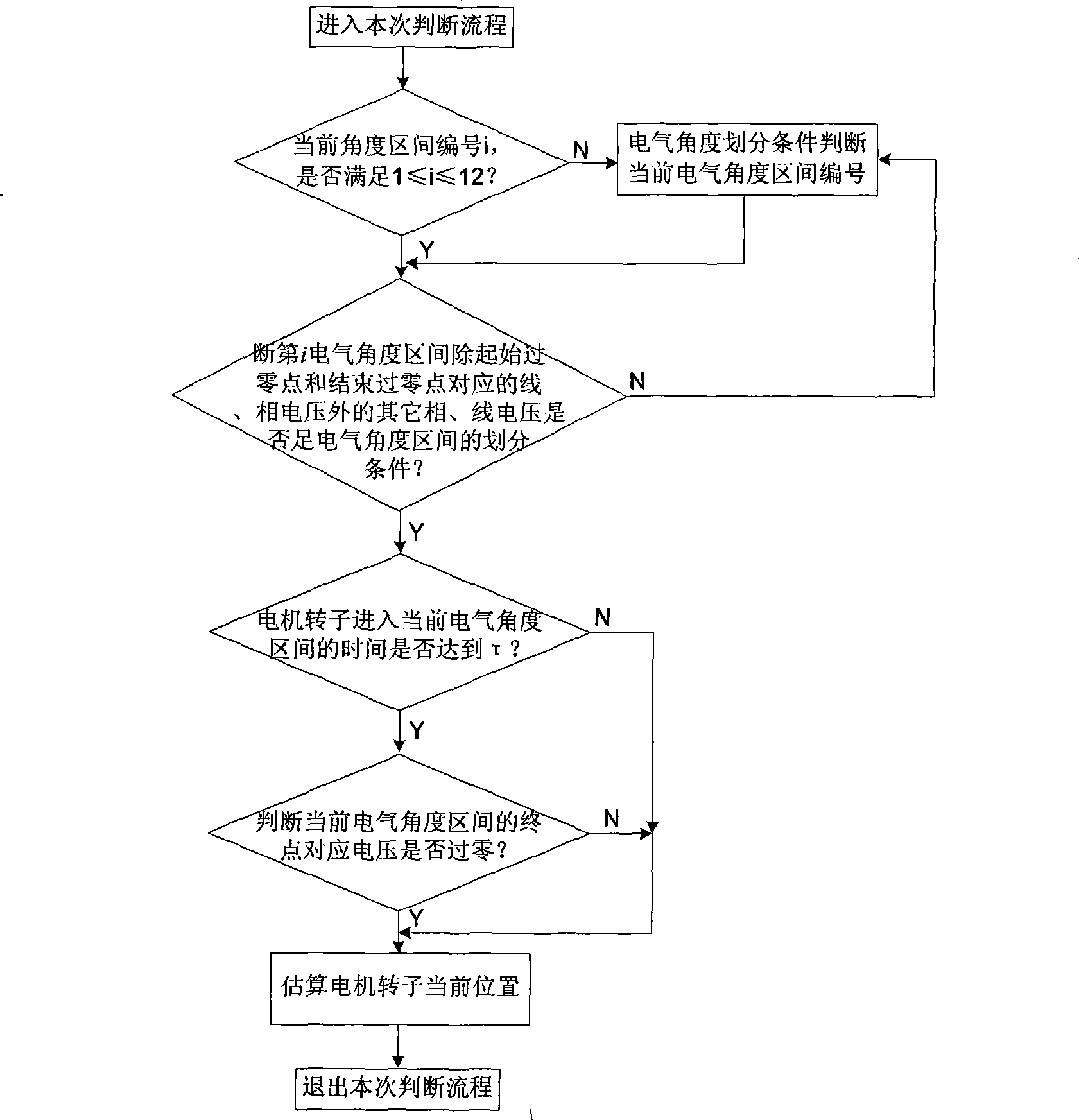
[0021] The present invention is a method for estimating and correcting the rotor position of a permanent magnet synchronous generator. The method divides the motor rotor 360° electrical angle into 12 electrical angle intervals in sequence with the motor terminal phase voltage and line voltage zero crossing point as the boundary (Such as figure 1 ), the 12 electrical angle intervals are sequentially recorded as the first to the twelfth electrical angle intervals, and the starting point of the first electrical angle interval is the 0° electrical angle of the motor, and each electrical angle interval backward The angle corresponding to the starting point of the angle interval is increased by 30° electrical angle in turn. The specific steps of this method are as follows, see the flowchart figure 2 :
[0022] (1). Set the current electrical angle interval number to the number of the electrical angle interval judged in the previous cycle and set it to i. If 1≤i≤12 is satisfied, go to step (3), if i does not satisfy 1≤i≤12 , Then go to step (2); if it is the first time to estimate the position of the motor rotor, go directly to step (2);
[0023] (2) Use the electrical angle division condition to determine the number i of the electrical angle interval where the rotor is currently located, and go to step (3);
[0024] (3) Determine whether the relative relationship between the two-phase line voltage and the relative relationship between the two-phase phase voltage and zero except the line and phase voltages corresponding to the initial zero-crossing point and the end zero-crossing point in the i-th electrical angle interval meets the division of the electrical angle interval If the conditions are met, the starting point of the electrical angle interval where the rotor is located corresponds to the electrical angle θ i_start =(i-1)×30°, and go to step (4), if not satisfied, go to step (2);
[0025] (4) Determine whether the time for the generator rotor to enter the current electrical angle interval reaches τ, the value range of the time parameter τ is 0
[0026] (5) Judge whether the corresponding voltage at the end of the current electrical angle interval crosses zero, if it is not zero, go directly to step (6); if it crosses zero, set the next electrical angle interval as the current electrical angle interval of the rotor , The current electrical angle interval number is j, which satisfies j = i + 1 i ≤ 11 1 i = 12 , The starting point of the electrical angle interval at this time corresponds to the electrical angle θ j_start =(j-1)×30°, and go to step (6);
[0027] (6) According to the average period value T of n consecutive electrical angle intervals in step (4), the electrical speed ω=π/(3*T) of the motor rotor can be obtained, and the time when the motor rotor enters the current angle interval is t0, in the xth interval of the current electrical angle interval, the electrical angle increment Δθ of the motor rotor position relative to the starting point of the interval x =ωt 0 =πt 0 /3T, the motor rotor estimates the position signal θ ^ = θ x _ start + Δ θ x .
[0028] The conditions for dividing the electrical angle interval are as follows:
[0029]Phase A voltage is less than or equal to zero, phase A line voltage is less than zero, phase B phase voltage is greater than zero, phase B line voltage is greater than zero, phase C phase voltage is less than zero, phase C line voltage is less than zero, meeting the above conditions is the first electrical angle Interval: Phase A phase voltage is less than zero, Phase A line voltage is less than zero, Phase B phase voltage is greater than zero, Phase B line voltage is greater than zero, Phase C voltage is less than zero, Phase C voltage is greater than or equal to zero, and the above conditions are met as the second Electrical angle interval; phase A voltage is less than zero, phase A line voltage is less than zero, phase B phase voltage is greater than zero, phase B line voltage is greater than zero, phase C voltage is greater than or equal to zero, phase C line voltage is greater than zero, and the above conditions are met The third electrical angle interval: Phase A voltage is less than zero, Phase A line voltage is less than zero, Phase B phase voltage is greater than zero, Phase B line voltage is less than or equal to zero, Phase C voltage is greater than or equal to zero, Phase C line voltage is greater than zero, which meets the above requirements The condition is the fourth electrical angle interval; phase A voltage is less than zero, phase A line voltage is less than zero, phase B phase voltage is less than or equal to zero, phase B line voltage is less than zero, phase C voltage is greater than or equal to zero, phase C line voltage is greater than zero, Meeting the above conditions is the fifth electrical angle interval; Phase A voltage is less than zero, Phase A line voltage is greater than or equal to zero, Phase B phase voltage is greater than zero, Phase B line voltage is less than zero, Phase C voltage is greater than or equal to zero, Phase C voltage is greater than Zero, meeting the above conditions is the sixth electrical angle interval; Phase A voltage is greater than or equal to zero, Phase A line voltage is greater than zero, Phase B phase voltage is less than zero, Phase B line voltage is less than zero, Phase C voltage is greater than zero, Phase C line If the voltage is greater than zero, meeting the above conditions is the seventh electrical angle interval; phase A phase voltage is greater than zero, phase A line voltage is greater than zero, phase B phase voltage is less than zero, phase B line voltage is less than zero, phase C voltage is greater than zero, C Phase line voltage is less than or equal to zero, and the above conditions are met as the eighth electrical angle interval; phase A phase voltage is greater than zero, phase A line voltage is greater than zero, phase B phase voltage is less than zero, phase B line voltage is less than zero, phase C voltage is less than or equal to zero , Phase C line voltage is less than zero, and the above conditions are met as the ninth electrical angle interval; Phase A voltage is greater than zero, Phase A line voltage is greater than zero, Phase B phase voltage is less than zero, Phase B line voltage is greater than or equal to zero, Phase C voltage Less than zero, C-phase line voltage is less than zero, and the above conditions are met as the tenth electrical angle interval; A-phase voltage is greater than zero, A-phase line voltage is greater than zero, B-phase voltage is greater than or equal to zero, B-phase line voltage is greater than zero, C-phase Phase voltage is less than zero, phase C line voltage is less than zero, meeting the above conditions is the eleventh electrical angle interval; phase A phase voltage is greater than zero, phase A line voltage is less than or equal to zero, phase B phase voltage is greater than zero, phase B line voltage is greater than zero , C-phase phase voltage is less than zero, C-phase line voltage is less than zero, meeting the above conditions is the twelfth electrical angle interval. From figure 1 It can be seen that the zero-crossing point where the phase A voltage value changes from negative to positive is the starting point, the zero-crossing point where the line voltage value of phase C and A phase changes from positive to negative as the end point, and the area between the two points is taken as the first electrical angle Interval. In each electrical angle interval, the three-phase voltage line-phase voltage has certain characteristics. By judging each voltage, the electrical angle interval of the current motor rotor can be obtained. In each electrical angle interval, the relative relationship between three-phase phase voltage, line voltage and zero is used as a general judgment method for judging the electrical angle interval of the motor rotor. For example, the three-phase phase voltage satisfies phase A in the first electrical angle interval Phase voltage is less than or equal to zero, phase A line voltage is less than zero, phase B phase voltage is greater than zero, phase B line voltage is greater than zero, phase C phase voltage is less than zero, phase C line voltage is less than zero, meeting the above conditions is the first electrical angle interval. The current electrical angle interval is judged by the above method. Once the first electrical angle interval is obtained, a special judgment flow is entered, namely step (3) to step (6), to judge the current electrical angle interval of the motor rotor.
[0030] In order to obtain an accurate motor rotor position signal, the present invention also proposes two methods for estimating the position deviation of the motor rotor.
[0031] The first deviation correction method (see Figure 4 ):
[0032] Take the current estimated position signal as a reference, establish a d-q rotating coordinate system, and extract the physical quantity voltage deviation Δu=u that contains the position deviation information in this coordinate system d +R·i d -ω·L·i q , Where u d , I d Are d-axis voltage and current respectively, i q Is the q-axis current, ω is the electrical angular velocity of the motor rotor, R and L are the resistance and inductance of the motor stator respectively, and the voltage deviation Δu is used as the feedback value of the basic position signal correction link, and the final compensation is obtained through PI adjustment Angle Δθ, and finally get an accurate motor rotor position signal θ=θ x_start +Δθ x +Δθ.
[0033] The second deviation correction method (see Figure 5 ):
[0034] Use the current estimated position signal as a reference to establish a d-q rotating coordinate system, in which high-frequency voltage signals are injected into the d-axis You can get the physical quantity current deviation including the position deviation among them, For the q-axis high frequency response current, BSF is a band-stop filter, and the current deviation Δi is used as the feedback value of the basic position signal correction link, and the final compensation angle Δθ is obtained through PI adjustment, and finally the accurate motor rotor position is obtained Signal θ=θ x_start +Δθ x +Δθ.
[0035] Accurate position signals can be obtained through these two deviation correction methods.
[0036] The present invention has been tested on a 50Kw direct-drive dynamic model generator set, in which a permanent magnet synchronous generator is used as the generator. The rotor position estimation method and the position correction method 1 of the permanent magnet synchronous generator of the present invention are used to estimate the rotor position of the permanent magnet direct drive generator, and experiments are carried out in the range of electric speed of 5-30 Hz.
[0037] Attached Figure 6 It is the generator terminal three-phase voltage, line voltage, actual position signal, and estimated position signal waveform recorded by the self-developed wave recording tool. As shown in the figure, according to the terminal voltage characteristics of the generator output, the 12 electrical angle intervals of the permanent magnet synchronous generator are determined according to the electrical angle interval division method proposed in the present invention. In the first angle interval of any divided electrical angle interval, the electrical angle θ of the cut-in point 1_start , The angle difference between any point A and the cut-in point in the interval is Δθ 1 , Then the electrical angle of point A can be obtained as θ ^ = θ 1 _ start + Δ θ 1 , By this method, the electrical angle of each point in the 12 intervals can be obtained, and the basic position signal of the motor rotor can be obtained. It can be seen from the figure that there is a certain phase difference between the estimated basic position signal of the motor rotor and the actual position signal.
[0038] The experiment uses the position correction method 1 to correct the phase difference between the basic position signal and the actual position signal. The corrected estimated position signal and actual position signal waveforms are as attached Figure 7 As shown, point A in the first angle interval is substantially coincident with the actual position after position correction, thereby realizing an accurate estimation of the motor rotor position.

PUM

no PUM

Description & Claims & Application Information

We can also present the details of the Description, Claims and Application information to help users get a comprehensive understanding of the technical details of the patent, such as background art, summary of invention, brief description of drawings, description of embodiments, and other original content. On the other hand, users can also determine the specific scope of protection of the technology through the list of claims; as well as understand the changes in the life cycle of the technology with the presentation of the patent timeline. Login to view more.

Similar technology patents

Aluminum-silicon alloy refining agent and preparation thereof

Owner:营口经济技术开发区金达合金铸造有限公司

Classification and recommendation of technical efficacy words

  • Easy to implement
  • Strong anti-interference ability

Ice layer thickness sensor and its detecting method

InactiveCN1560560AStrong anti-interference abilityMechanical thickness measurementsElectrical/magnetic thickness measurementsContactorIntermediate space
Owner:TAIYUAN UNIV OF TECH
Why Eureka
Try Eureka