Sliding guide rolling unloading device

A technology of unloading device and sliding guide rail, which is used in large fixed members, metal processing machinery parts, metal processing equipment, etc., can solve the problems of high requirements for lubrication, large contact area, large resistance, etc., and achieve high contact stiffness. , high motion sensitivity, the effect of reducing the friction area

Inactive Publication Date: 2009-08-19
DALIAN MACHINE TOOL GROUP CO LTD
View PDF0 Cites 7 Cited by
  • Summary
  • Abstract
  • Description
  • Claims
  • Application Information

AI Technical Summary

Problems solved by technology

The existing seed setting mechanisms are all surface contact, that is, the bottom surface of the slide seat and the top of the guide rail rub against each other, the contact area is large, the resistance during the movement is large, and there are high requirements for lubrication at the same time

Method used


Image

  • Sliding guide rolling unloading device
  • Sliding guide rolling unloading device

Examples


Embodiment Construction

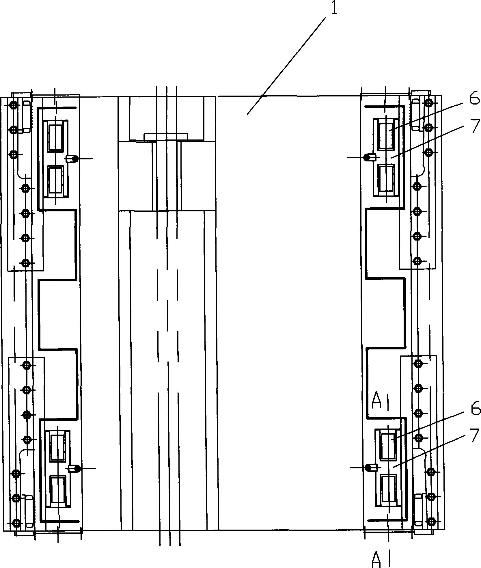
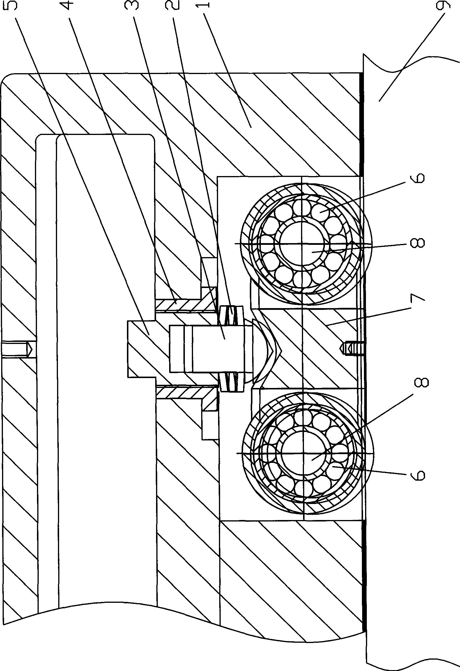
[0012] Such as figure 1 , 2 Shown: 1 is the sliding seat located above the basic guide rail 9 of the bed, on the bottom surface of the sliding seat 1 there are at least three positions that are matched with the guide rail, and rollers 6 are installed, and the outer surface of the circumference of the roller 6 is in contact with the upper surface of the guide rail below. touch. In this embodiment, rollers 6 are installed on the bottom surface of the four corners of the slide 1, and the slide 1 is supported on the guide rail by the roller 6, which unloads most of the gravity of the workbench and realizes the line contact with the guide rail. The guiding structure when the sliding seat 1 moves relative to the guide rail can be the same as the guiding structure in the prior art.

[0013] A fixed sleeve 4 is installed on the sliding seat 1, and the lower end of the fixed sleeve 4 has a boss for axial positioning. The support sleeve 5 is threadedly connected with the fixed sleeve...


PUM


Abstract

The invention discloses a sliding device, in particular a slide guide rail rolling and unloading device for machine tool equipment. The device comprises a guide rail and a slide seat (1) which is positioned on the guide rail and can slide relative to the guide rail, and is characterized in that: at least three positions matched with the guide rail on the bottom surface of the slide seat (1) are provided with roller wheels (6), and the circumferential lateral surfaces of the roller wheels (6) are contacted with the upper surface of the guide rail positioned under the slide seat (1). In the device, as the slide seat and the guide rail do not directly contact, are supported by the roller wheel, and slide, the device realizes line contact of the roller wheel and the guide rail, greatly reduces the mutual friction area, reduces moving resistance, saves energy and lowers the requirement on lubrication compared with a sliding mode of surface contact.

Description

technical field [0001] The invention relates to a sliding device, in particular to a sliding guide rail rolling unloading device used on machine tool equipment. Background technique [0002] At present, sliding mechanisms are often used on machine tool equipment, that is, guide rails are provided below, slide seats are provided above the guide rails, and relevant equipment components are installed above the slide seats. When working, under the action of the driving mechanism, the sliding seat moves on the guide rail. The existing seed setting mechanisms are of the surface contact type, that is, the bottom surface of the sliding seat and the upper surface of the guide rail rub against each other, the contact area is large, the resistance during the movement is large, and there are high requirements for lubrication. Contents of the invention [0003] The purpose of the present invention is to provide a sliding guide rail rolling unloading device that does not directly conta...

Claims


Application Information

Patent Timeline
Patent Type & Authority Applications(China)
IPC IPC(8): B23Q1/40
Inventor 佟万成张树礼周建吴平孟祥东
Owner DALIAN MACHINE TOOL GROUP CO LTD
Why Eureka
Try Eureka