A kind of high-speed cutting mechanism and using method of bt tool holder

A high-speed cutting and tool handle technology, which is applied in the direction of metal processing machinery parts, clamping, support, etc., can solve the problems of poor quality of machined parts, low axial positioning accuracy, and easy damage of tools, so as to reduce tool wear and improve machining Accuracy and processing efficiency, and the effect of improving the service life

Active Publication Date: 2017-09-05
JIANGSU YUANLI AVIA PRECISION MACHINE TOOL
View PDF2 Cites 0 Cited by
  • Summary
  • Abstract
  • Description
  • Claims
  • Application Information

AI Technical Summary

Problems solved by technology

[0008] Aiming at the problems of low axial positioning accuracy, poor quality of machined parts and easy damage of tools in the prior art during high-speed machining of BT tool holders, the present invention provides a high-speed cutting mechanism and usage method of BT tool holders, which enable BT tool holders to realize High-speed cutting, and during high-speed cutting processing, the contact stiffness and repeat positioning accuracy of BT tool holder are high, and the high-speed cutting performance is reliable; at the same time, the radial tool holder positioning system with closed structure avoids the vibration and tilt of the tool holder and improves the machining accuracy and efficiency, reducing tool wear and increasing tool and machine tool life

Method used


Image

  • A kind of high-speed cutting mechanism and using method of bt tool holder

Examples


Embodiment 1

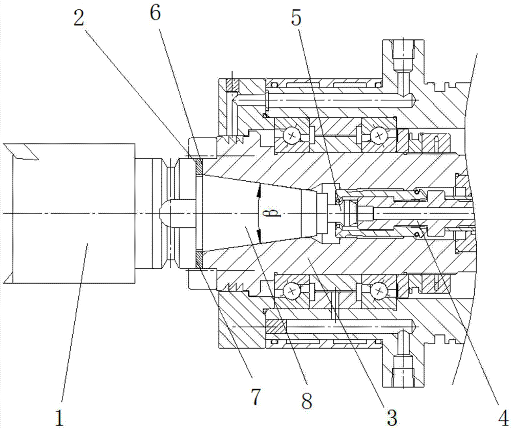
[0042] Such as figure 1 As shown, a BT handle high-speed cutting mechanism of this embodiment includes a BT handle 1, a main shaft 3, a broach mechanism 4, a pull nail 5 and a pad cover 2, and the end face of the non-tool mounting end of the BT handle 1 is a knife The rear end face 7 of the shank is provided with a cone 8 at the center of the rear end face 7 of the handle, and the pull stud 5 is connected to the center position of the end face of the truss 8 through threads; The end face is the front end face 6 of the spindle, and a taper hole is provided at the center of the front end face 6 of the spindle. The shape of the taper hole matches the truncated cone 8, which is installed in the taper hole; Between the front end faces 6 , the material of the cushion cover 2 in this embodiment is 40CrNi, the broach mechanism 4 is installed in the central cavity of the main shaft 3 , and the broach mechanism 4 is engaged with the pull rivet 5 .

[0043] In the present embodiment, th...

Embodiment 2

[0055] Basically the same as Embodiment 1, the difference is that the working tension F of the broach mechanism 4 max =10000N, the thickness of the obtained cushion sleeve 2 is L=4.007mm, that is, the thickness of the cushion sleeve 2 is greater than the distance between the rear end surface 7 of the tool holder and the front end surface 6 of the main shaft L-k=0.007mm, and the radial runout of the BT tool holder 1 is less than 0.001mm, the service life of BT toolholders is increased by 77%, and the service life of machine tools is increased by 65%.

Embodiment 3

[0057] Basically the same as Embodiment 1, the difference is that the working tension F of the broach mechanism 4 max =12000N, the thickness of the obtained cushion sleeve 2 is L=4.009mm, that is, the thickness of the cushion sleeve 2 is greater than the distance between the rear end surface 7 of the tool holder and the front end surface 6 of the spindle L-k=0.009mm, and the radial runout of the BT tool holder 1 is less than 0.001mm, the service life of BT toolholders is increased by 73%, and the service life of machine tools is increased by 72%.


PUM


Abstract

The invention discloses a BT knife handle high-speed cutting mechanism and a use method and belongs to the technical field of numerically-controlled machine tool cutting machining. The BT knife handle high-speed cutting mechanism comprises a BT knife handle, a main shaft, a knife pulling mechanism, a pop-rivet and a cushion cover, wherein the end face of the non tool installation end of the BT knife handle is a knife handle rear end face, a circular cone frustum is arranged on the center position of the knife handle rear end face, the pop-rivet is installed on the center position of the end face of the circular cone frustum, the main shaft is a hollow shaft, the end face of the end, close to the rear end face of the knife handle, of the main shaft is a main shaft front end face, a taper hole is formed in the center portion of the main shaft front end face, the shape of the taper hole is matched with that of the circular cone frustum, the circular cone frustum is installed in the taper hole, the cushion cover is arranged between the knife handle rear end face and the main shaft front end face, the knife pulling mechanism is installed in a main shaft center cavity, and the knife pulling mechanism is connected with the pop-rivet in a clamped mode. By means of the BT knife handle high-speed cutting mechanism and the use method, the high-speed cutting of the BT knife handle is achieved, the contact rigidity and the repeated positioning accuracy of the BT knife handle are high, the high-speed cutting machining precision and the efficiency are high, the service lives of a tool and a machine tool are prolonged, and the BT knife handle can replace an HSK knife handle to be used.

Description

technical field [0001] The invention belongs to the technical field of CNC machine tool cutting, and more specifically relates to a BT tool handle high-speed cutting mechanism and a use method. Background technique [0002] High-speed cutting is an advanced manufacturing technology that combines high efficiency, high quality and low consumption in the 21st century. A series of problems that have been plagued by conventional cutting have been solved through the application of high-speed cutting. High-speed cutting is not only the increase of the spindle speed, but also requires the cutting tool system to have high rigidity, safety, flexibility, dynamic balance characteristics and convenient operation; at the same time, the connection stiffness, precision and tool The handle puts forward very high requirements on the clamping force and clamping accuracy of the tool. Insufficient rigidity of the tool handle system will cause the tool system to vibrate or tilt, which will reduce...

Claims


Application Information

Patent Timeline
Patent Type & Authority Patents(China)
IPC IPC(8): B23Q3/12
CPCB23Q3/12
Inventor 王立民袁旎呼如亮吴亚辉朱云云杨凡
Owner JIANGSU YUANLI AVIA PRECISION MACHINE TOOL
Why Eureka
Try Eureka