Method for filling sandwich layer thermal insulating material for deep cooling container and special filling apparatus

A heat-insulating material and filling method technology, applied to pressure vessels, fixed-capacity gas storage tanks, mechanical equipment, etc., can solve problems such as dead angles of filling, increased difficulty of vacuuming, slow filling speed, etc., to ensure maintenance time and easy equipment , Guarantee the effect of filling speed and uniformity

Active Publication Date: 2009-08-19
SHANDONG HONGDA TECH GRP
View PDF1 Cites 3 Cited by
  • Summary
  • Abstract
  • Description
  • Claims
  • Application Information

AI Technical Summary

Problems solved by technology

Although the patented method is used, the air in the container and the moisture in the air also enter the filled area while filling the insulation material, which increases the difficulty of vacuuming in the later stage.
Similarly, the filling speed of this method is slow for large cryogenic containers, and it is easy to have a filling dead angle for sandwich structures with poor fluidity

Method used


Image

  • Method for filling sandwich layer thermal insulating material for deep cooling container and special filling apparatus

Examples


Embodiment 1

[0014] Embodiment 1, a method for filling the interlayer insulation material of a cryogenic container: mainly includes the following steps:

[0015] a. Fill the sealed filling material storage tank with nitrogen to discharge the air in it. For the humid environment, the tank should be heated to 140°C to ensure that the filling is dry.

[0016] b. Vacuumize the interlayer of the cryogenic container to below 30-50pa.

[0017] c. In the state of continuous vacuuming, slowly open the valve on the pipeline connecting the filling material storage tank and the interlayer of the cryogenic container, keep the nitrogen pressure at 0.2Mpa, and the filling material fills the interlayer of the cryogenic container under the pressure of nitrogen.

[0018] d. When filling to 80% of the design density, close the connecting valve and increase the pressure of the filling material tank to 0.6MPa. At the same time, the interlayer of the cryogenic container is vacuumed to 5-15Pa. Quickly open the...

Embodiment 2

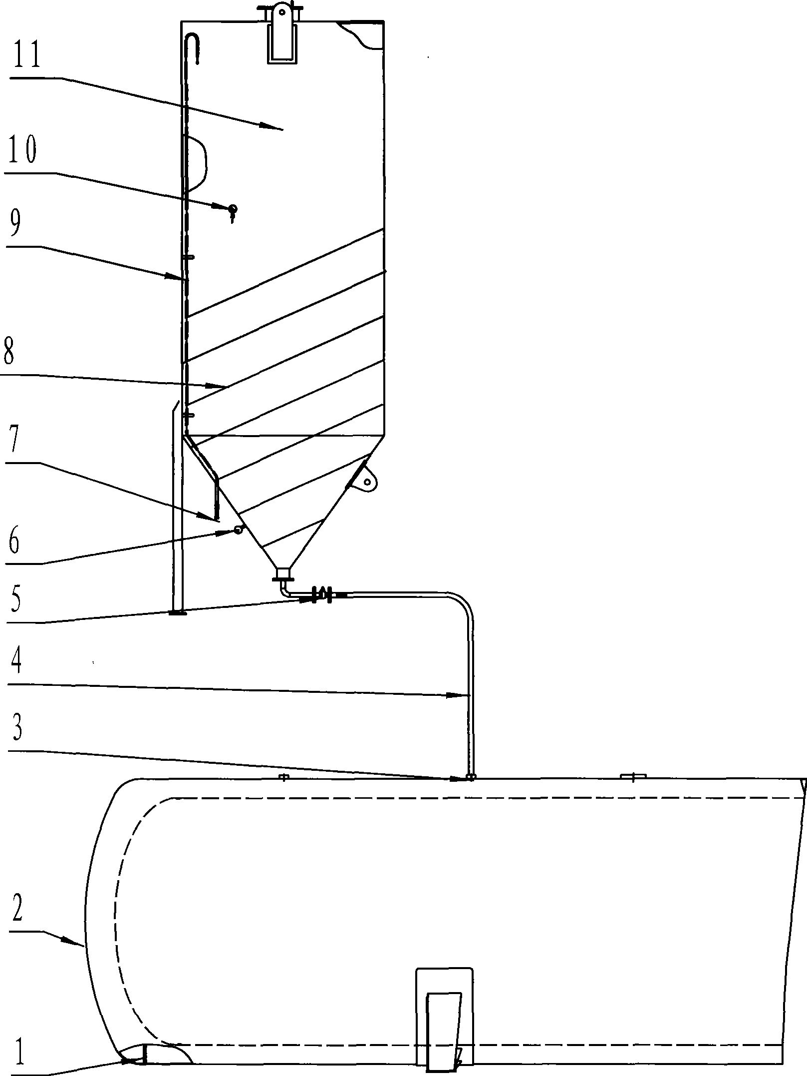
[0021] Embodiment 2, the special device used in the filling method of the interlayer insulation material of the cryogenic container, its structure is: a vertically installed filling material storage tank 11, the lower part is conical, and a pressure gauge 6 and a nitrogen inlet 7 are installed on the conical surface. The conveying pipe 9 goes upward along the tank body, and its outlet is on the top of the storage tank. The conical bottom end of the tank body is equipped with a filling material conveying pipe 4 connected to the filling material filling hole 3 of the cryogenic container 2. The conveying pipe is equipped with a quick-opening valve 5. The cryogenic container is provided with air extraction holes. When the environment is moderately large, first open the heating coil device 8, and then carry out the above filling work after the thermometer 10 shows that it rises to 140°C.


PUM


Abstract

The invention discloses a method for filling deep cooling container interlayer heat-insulating material, belonging to a method for placing diffluent solid material into a container and a device thereof, the method and the device for placing the solid material into a vacuum container in particular. The invention discloses a new technique in which nitrogen is used to replace air in a filling material storage tank and nitrogen pressure is used to fill heat-insulating material in the deep cooling container interlayer and discloses a specialized device matched with the technique. The bottom part of the filling material storage tank is of a conical structure, which facilitates filling the material. 0.2 MPa of nitrogen is infused into the store tank to prevent air from contacting with the filling material; the method of the invention ensures that in the process of filling, the filling material is not contacted with the air; meanwhile, multi-groups of store tanks can be filled simultaneously, thus filling speed and evenness are ensured; in addition, the method can replace the remaining air in the interlayer, ensuring future maintaining time of high vacuum in the interlayer; the method is simple and feasible and the equipment in the specialized device is easy to be manufactured.

Description

technical field [0001] The invention belongs to a method and a device for filling a fluid solid material into a container, especially a method and a device for filling a vacuum container. Background technique [0002] Cryogenic containers such as liquefied natural gas storage and transportation tanks, the interlayer between the outer shell and the inner tank is a high vacuum and filled with heat insulating materials. The air in the interlayer should also be fully replaced. How to fill the insulation material while maintaining the high vacuum of the interlayer is a difficult point in the cryogenic container manufacturing technology. The Chinese patent ZL93105291.2 owned by Japan Sharp Corporation discloses a packing container and a packing filling device for vacuum insulation As for the filling method thereof, the container is composed of a sheet-shaped cover made of an air-permeable material and a container main body. Fill the packing container evenly and densely through a...

Claims


Application Information

Patent Timeline
Patent Type & Authority Applications(China)
IPC IPC(8): F17C1/12
Inventor 付资兑谢占坤
Owner SHANDONG HONGDA TECH GRP
Why Eureka
Try Eureka