Stand type LED fluorescent lamp

A technology of LED fluorescent lamps and LED light sources, which is applied to light sources, electric light sources, point light sources, etc., can solve the problems of unsatisfactory local heat dissipation performance, inability to realize multiple lamps in series, and rapid temperature rise of lamp tubes, etc., to prevent the LED temperature from rising. High problem, simple and compact structure, energy saving effect

Inactive Publication Date: 2009-08-19
MIANYANG NENGSHI GUANGBAO ELECTRONICS
View PDF0 Cites 6 Cited by
  • Summary
  • Abstract
  • Description
  • Claims
  • Application Information

AI Technical Summary

Problems solved by technology

[0003] As we all know, the commonly used fluorescent lamps use electric heating filaments to excite the gas in the lamp tube to emit light. This kind of fluorescent lamps consumes high energy, has short service life, and wastes seriously pollute the environment. In order to solve the above problems, people have developed in recent years. Light-emitting diodes replace gas to emit light. Its basic structure includes a glass lamp tube with two open ends, two end caps assembled with the lamp tube openings, two conductive electrodes on the end caps, and a circuit board, constant current driver and Several LEDs, the circuit board is arranged axially in the glass lamp tube, the two

Method used


Image

  • Stand type LED fluorescent lamp
  • Stand type LED fluorescent lamp
  • Stand type LED fluorescent lamp

Examples


Example Embodiment

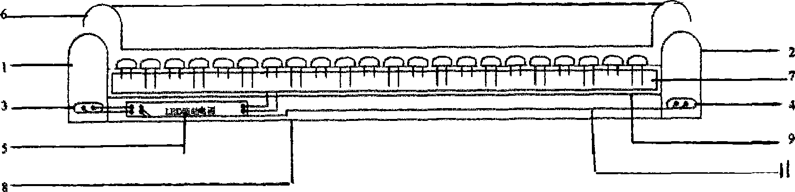
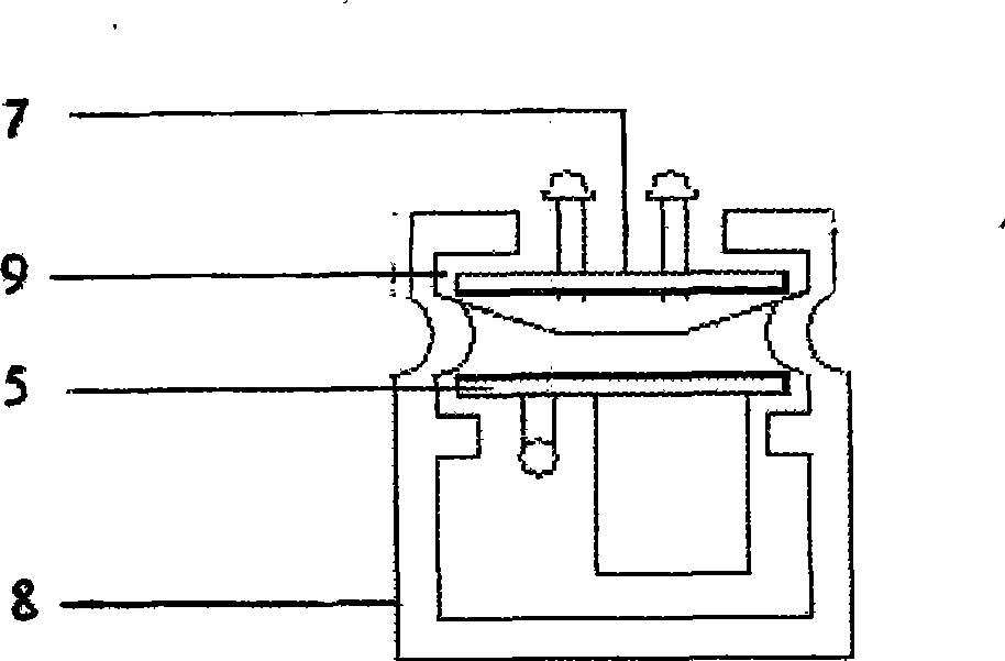
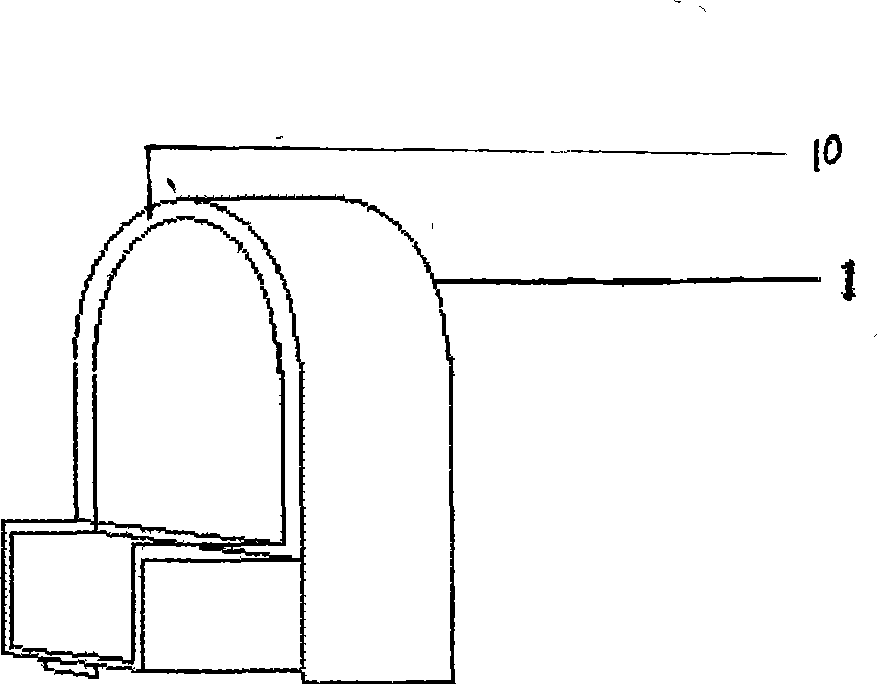
[0019] Example 1, such as figure 1 , figure 2 As shown, the present invention includes a lamp body 8, which is connected to the input and output ends of the bracket and is provided with terminals 1 and 2 of conductive terminals 3 and 4. The lower part of the terminals is provided with a tongue, and the outer diameter of the tongue is consistent with the cavity of the bracket. , so that the two can be plugged together. LED light source circuit board 9, constant current driving power supply (driver) 5, support 8 is a bar-shaped groove body with a boss, and the two walls of the upper part of the bracket seat cavity are provided with LED light source circuit board slots, which are plugged with LED light source circuit board 7 Then, of course, the same purpose can also be achieved by providing parallel bumps on the cavity walls on both sides. The LED light source circuit board is composed of light-emitting diodes and printed circuits on the back of the PCB board. The distance be...

Example Embodiment

[0020] Example 2, such as figure 1 , figure 2 As shown, the present invention includes a lamp body, which is connected to the input and output ends of the bracket and is provided with terminals 1 and 2 of conductive terminals 3. The lower part of the terminals is provided with a tongue, and the outer diameter of the tongue is consistent with the bracket cavity, so that the two plugged in. LED light source circuit board 9, constant current drive power supply (driver) 5, support 8 is the bar-shaped groove body of a band boss, and the side chamber wall on two walls of support base cavity top is provided with parallel salient point, and LED light source circuit board 7 plugging, said LED light source circuit board is made of light-emitting diode and the printed circuit welding of PCB board back side. The distance between the neck of the light-emitting diode on the LED light source circuit board and the top of the PCB is 5mm, that is, the diode feet are exposed to the surface of...

Example Embodiment

[0021] Example 3, such as figure 1 , figure 2 As shown, the present invention includes a lamp body, which is connected to the input and output ends of the bracket and is provided with terminals 1 and 2 of conductive terminals 3. The lower part of the terminals is provided with a tongue, and the outer diameter of the tongue is consistent with the bracket cavity, so that the two plugged in. LED light source circuit board 9, constant current driving power supply (driver) 5, support 8 is a bar-shaped groove body with a boss, and the two walls of the upper part of the bracket seat cavity are provided with LED light source circuit board slots, which are plugged with LED light source circuit board 7 Then, of course, the same purpose can also be achieved by providing parallel bumps on the cavity walls on both sides. The LED light source circuit board is composed of light-emitting diodes and printed circuits on the back of the PCB board. The distance between the neck of the light-em...


PUM


Abstract

The invention discloses a bracket-type LED fluorescent lamp, comprising a lamp body, terminations (1), (2) that are connected with the input and output two end parts of a bracket and that are provided with conductive terminals (3), (4), an LED light source circuit board (9), a constant-current drive power source (5); characterized in that: the lamp body is integrated with the bracket (8) as a whole, the bracket is a bar-shaped groove with a lug boss, slots of the LED light source circuit board are provided on two walls of the upper part of a cavity of the bracket and are spliced with an LED light source circuit board (7); on the LED light source circuit board, a spacing of the upper part of a PCB board of a light emitting diode is 4-7 mm, the constant-current drive power source is fixed at the lower part of the cavity of the bracket, two sides of the bracket is in clamping connection with the lower part of a transparent cover (6), the constant-current drive power source is connected via a lead wire (11) with the conductive terminals on the input and output two end parts and with the LED light source circuit board, respectively. The lamp is little in energy consumption, convenient in usage, simple and compact in structure, eye-pleasing in appearance and long in service life.

Description

[0001] Field [0002] The invention relates to an illuminating device, in particular to a bracket type LED fluorescent lamp. Background technique [0003] As we all know, the commonly used fluorescent lamps use electric heating filaments to excite the gas in the lamp tube to emit light. This kind of fluorescent lamps consumes high energy, has short service life, and wastes seriously pollute the environment. In order to solve the above problems, people have developed in recent years. Light-emitting diodes replace gas to emit light. Its basic structure includes a glass lamp tube with two open ends, two end caps assembled with the lamp tube openings, two conductive electrodes on the end caps, and a circuit board, constant current driver and Several LEDs, the circuit board is arranged axially in the glass lamp tube, the two ends of the circuit board are respectively assembled with the end caps located at both ends of the glass lamp tube, the constant current driver is installed on...

Claims


Application Information

Patent Timeline
IPC IPC(8): F21S8/00F21V19/00F21V23/00F21V23/06F21Y101/02F21Y103/00F21Y115/10
Inventor 青春茂
Owner MIANYANG NENGSHI GUANGBAO ELECTRONICS
Why Eureka
Try Eureka