Self-demarcating system and method for vision detecting system
A visual inspection and self-calibration technology, applied in the field of calibration systems, can solve the problems of poor stability and reliability, the existence of moving parts, slow speed, etc., to achieve good stability, long life, and solve the effect of inaccurate zoom.
- Summary
- Abstract
- Description
- Claims
- Application Information
AI Technical Summary
Problems solved by technology
Method used
Image

Examples
Embodiment 1
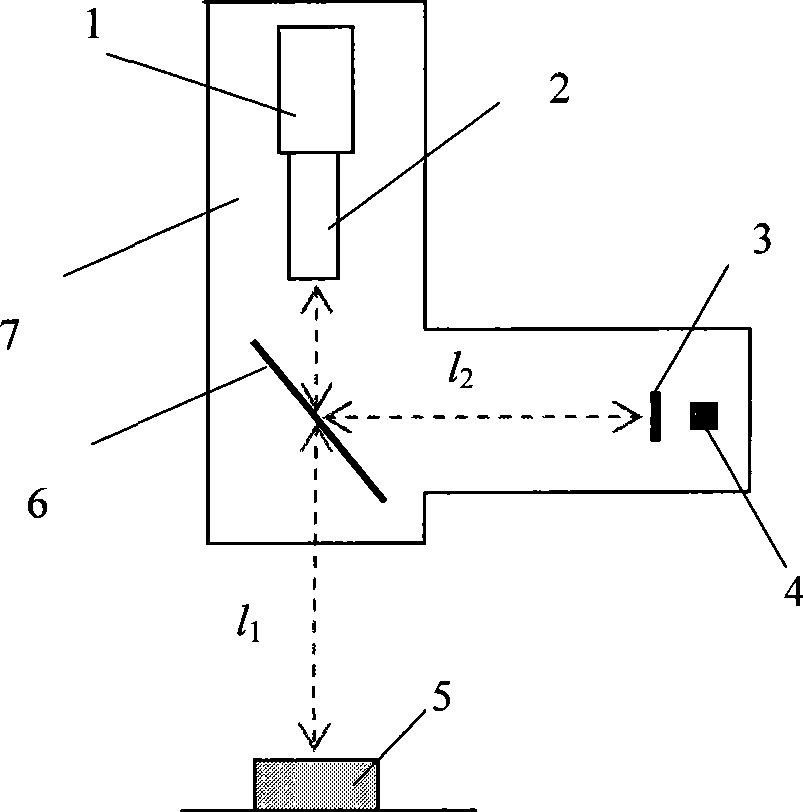
[0036] Such as figure 1 As shown, the self-calibration system for the visual inspection system involved in this embodiment includes a CCD camera 1 , a lens 2 , a standard part 3 , a light source 4 , a half mirror 6 and a housing 7 . The lens 2 is directly connected with the camera 1 , placed directly above the test piece 5 , and aimed at the test piece 5 . A half mirror 6 is placed between the lens 2 and the tested object 5, and forms an angle of 45 degrees with the optical axis of the lens 2. A distance from the side of the half mirror 6 is provided with a standard part 3 and a light source 4, wherein the light source 4 and the half mirror 6 are located on different sides of the standard part 3, and the half mirror, the standard part and the light source are three The formed calibration light path is orthogonal to the original measurement light path. All the above-mentioned components are fixed on the casing 7, so as to ensure a strict mutual positional relationship, and at...
Embodiment 2
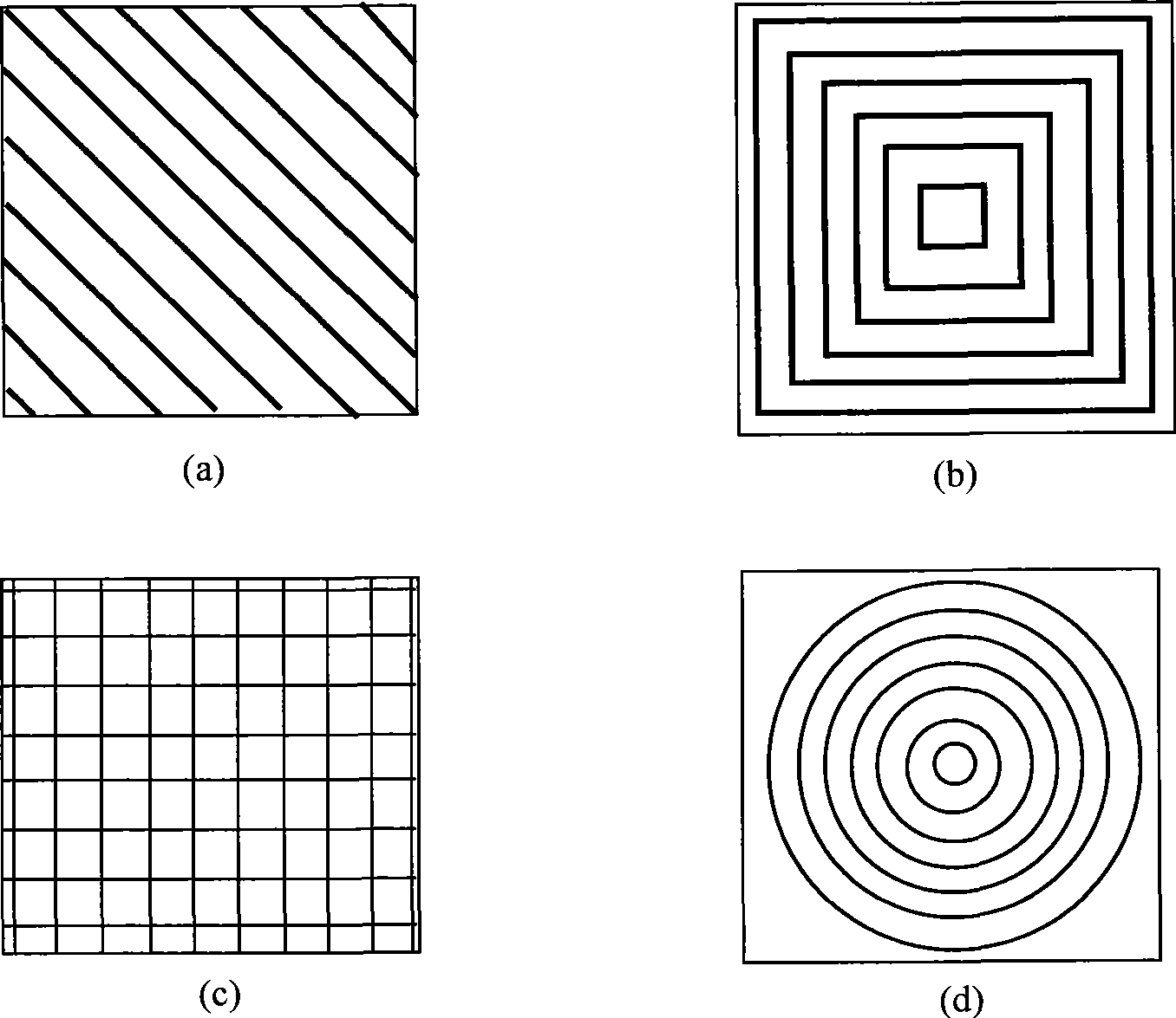
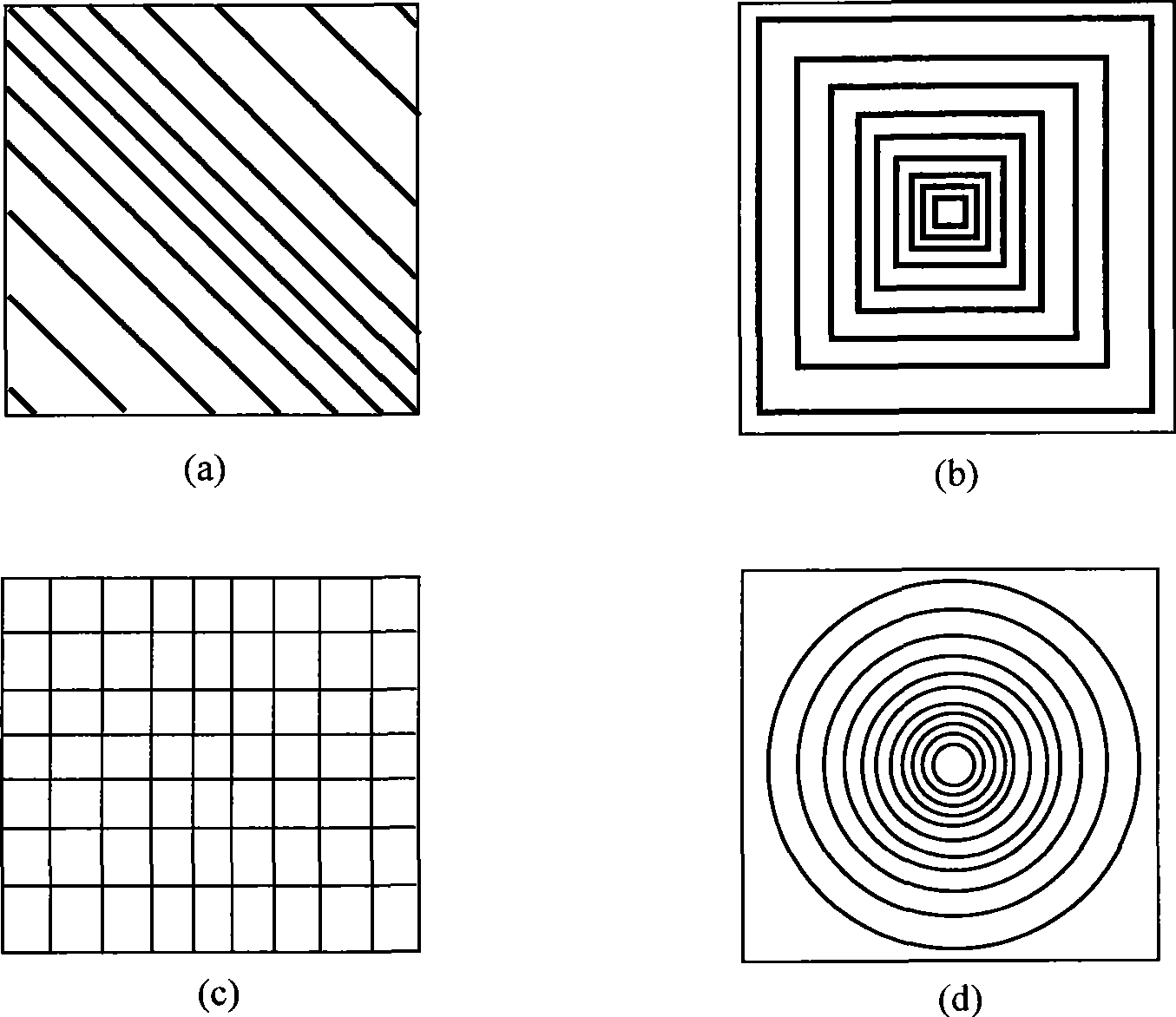
[0047] Such as Figure 4 As shown, the self-calibration system for the visual inspection system involved in the present embodiment includes a CCD camera 1, a lens 2, a standard part 3, a light source 4, a half-mirror 6 and a housing 7, a plane mirror 8, and the lens 2 and The camera 1 is directly connected, placed directly above the DUT 5 , and aimed at the DUT 5 . A half mirror 6 is placed between the lens 2 and the tested object 5, and forms an angle of 45 degrees with the optical axis of the lens 2. Both the standard part 3 and the light source 4 are arranged beside the lens 2 and the camera 1, and the centerlines of the standard part 3 and the light source 4 are parallel to the optical axes of the lens and the camera, and as close as possible. A flat reflector 8 is placed on the side where the standard part 3 and the light source 4 are arranged on the half mirror 6 . Wherein the standard part 3 is light-transmitting and has regular-shaped graphics on it. The image formed...
Embodiment 3
[0051] The self-calibration method for the visual inspection system involved in this embodiment includes the following steps:
[0052] 1. Adjust the lens 2 to ensure that the camera 1 can obtain a clear image and the size of the field of view, and then keep the lens 2 still;
[0053] 2. Turn on the light source 4, the regular pattern on the standard part is illuminated, and imaged on the CCD image plane of the camera 1 through the half mirror 6 and the lens 2;
[0054] 3. Perform necessary image processing and calculation to obtain the imaging size parameters of the above-mentioned regular graphics in the image coordinate system at the current magnification, and the unit is pixel;
[0055] 4. Comparing the imaging size parameters of the above-mentioned regular graphics with their actual size parameters, the corresponding relationship value (ie equivalent) between the two can be obtained, the unit is length / pixel, and the value is automatically saved in the computer.
[0056] ...
PUM
 Abstract
Description
Claims
Application Information
 - R&D
- Intellectual Property
- Life Sciences
- Materials
- Tech Scout
- Unparalleled Data Quality
- Higher Quality Content
- 60% Fewer Hallucinations
Browse by: Latest US Patents, China's latest patents, Technical Efficacy Thesaurus, Application Domain, Technology Topic, Popular Technical Reports.
© 2025 PatSnap. All rights reserved.Legal|Privacy policy|Modern Slavery Act Transparency Statement|Sitemap|About US| Contact US: help@patsnap.com