Roughing end mill and roughing end mill

A technology of end mills and blades, which is applied in the field of rough machining end mills with detachable blades, can solve the problems of surface roughness deterioration, cutting force reduction, chip handling damage, etc., to prevent significant damage to surface roughness, The effect of reduction of cutting force and improvement of chip disposal

Active Publication Date: 2013-01-09
MITSUBISHI MATERIALS CORP
View PDF5 Cites 0 Cited by
  • Summary
  • Abstract
  • Description
  • Claims
  • Application Information

AI Technical Summary

Problems solved by technology

[0010] Therefore, in this case, as an insert mounted on the top end of the end mill body, an insert with two short cutting edges is required, and the tip side portion of the wave-shaped cutting edge has the same shape and rear end. There are two types of inserts with long cutting edge lengths of different shapes that do not coincide with each other on the side parts, and there are three types of inserts in total. However, these two types of inserts with long cutting edge lengths are similar in shape to each other, so there is a possibility that the same insert is installed incorrectly. The problem
And, when such a mounting error occurs and the rotation trajectory of the wave-shaped cutting edge coincides at the part of the rear end side of the insert with a long cutting edge length, the wave-shaped cutting edge will turn to the processing surface of the workpiece as described above. Even though it is rough machining, it forms a machined surface with large unevenness, and the surface roughness is significantly deteriorated. In the subsequent finishing machining, it is necessary to increase the amount of finishing machining, and it also damages the reduction of cutting force and chip handling.

Method used


Image

  • Roughing end mill and roughing end mill
  • Roughing end mill and roughing end mill
  • Roughing end mill and roughing end mill

Examples


Embodiment Construction

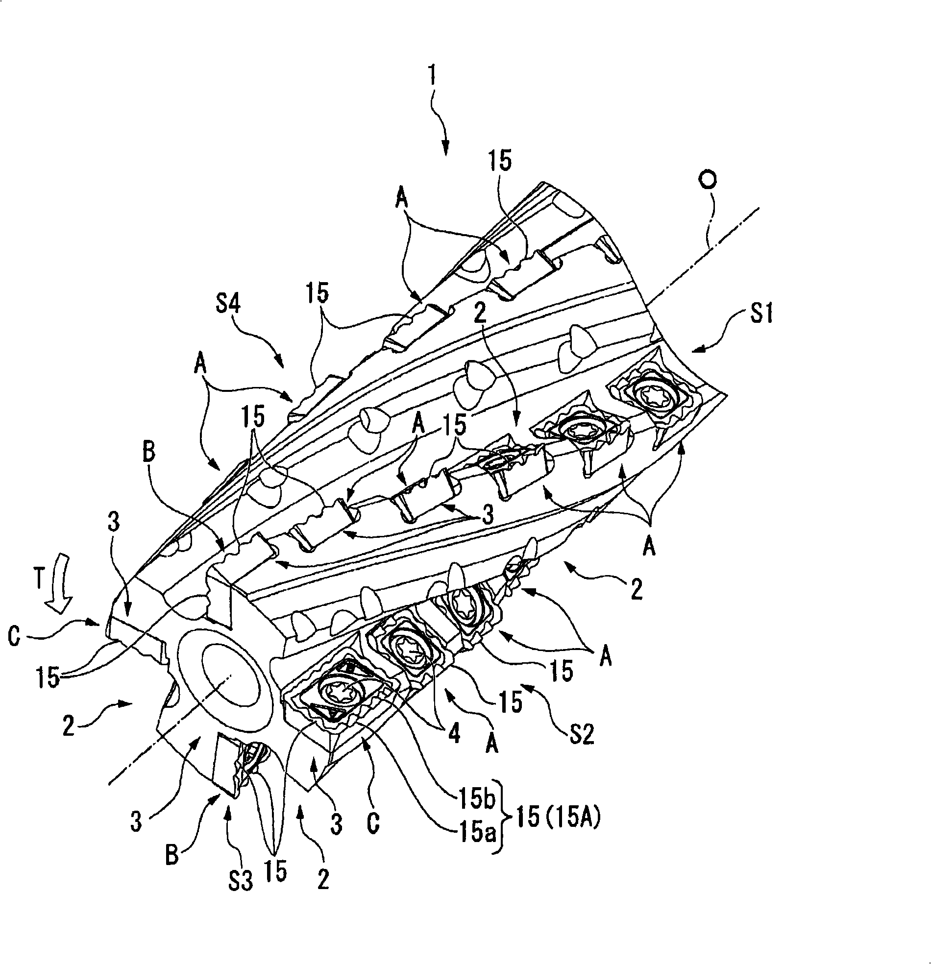
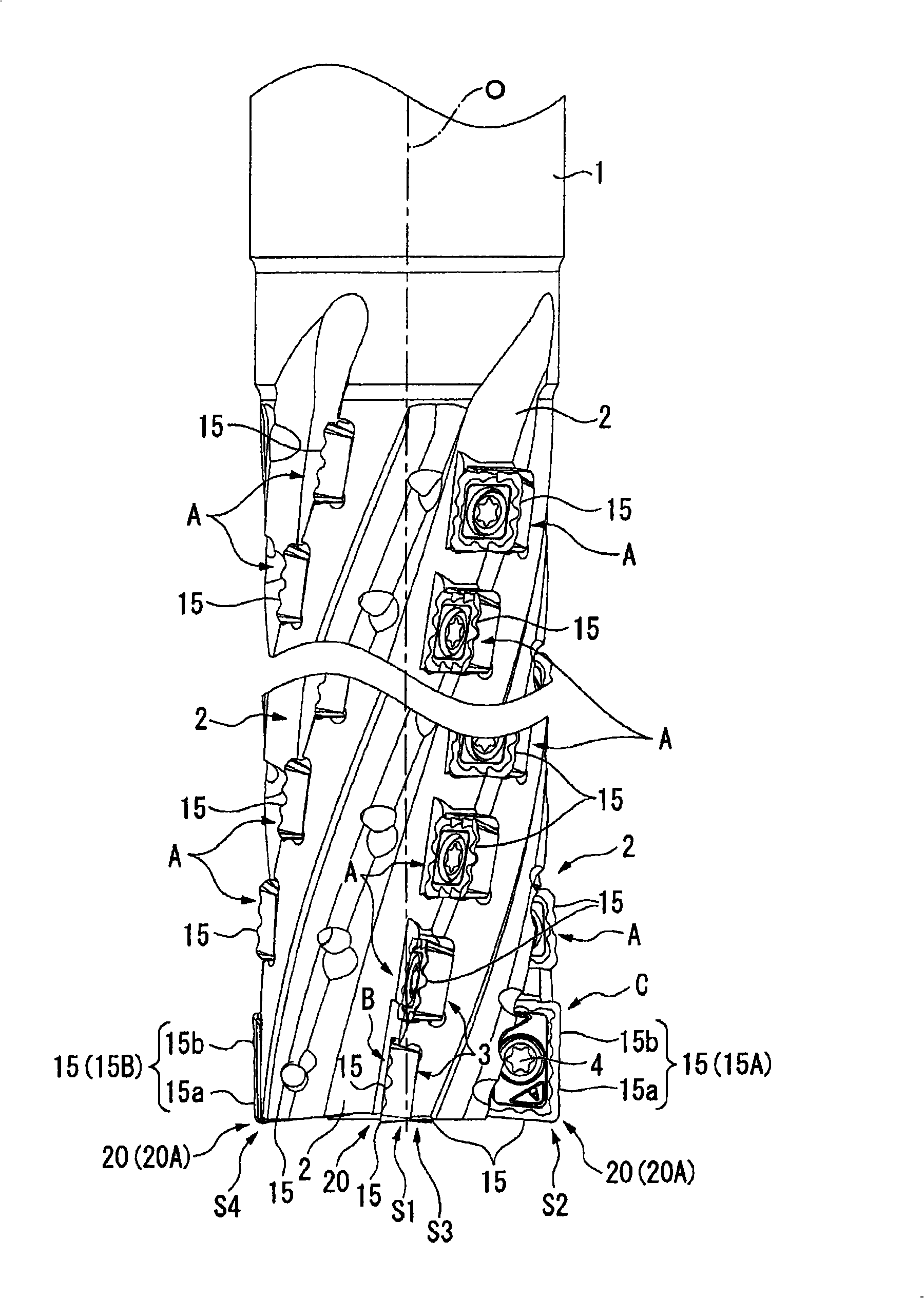
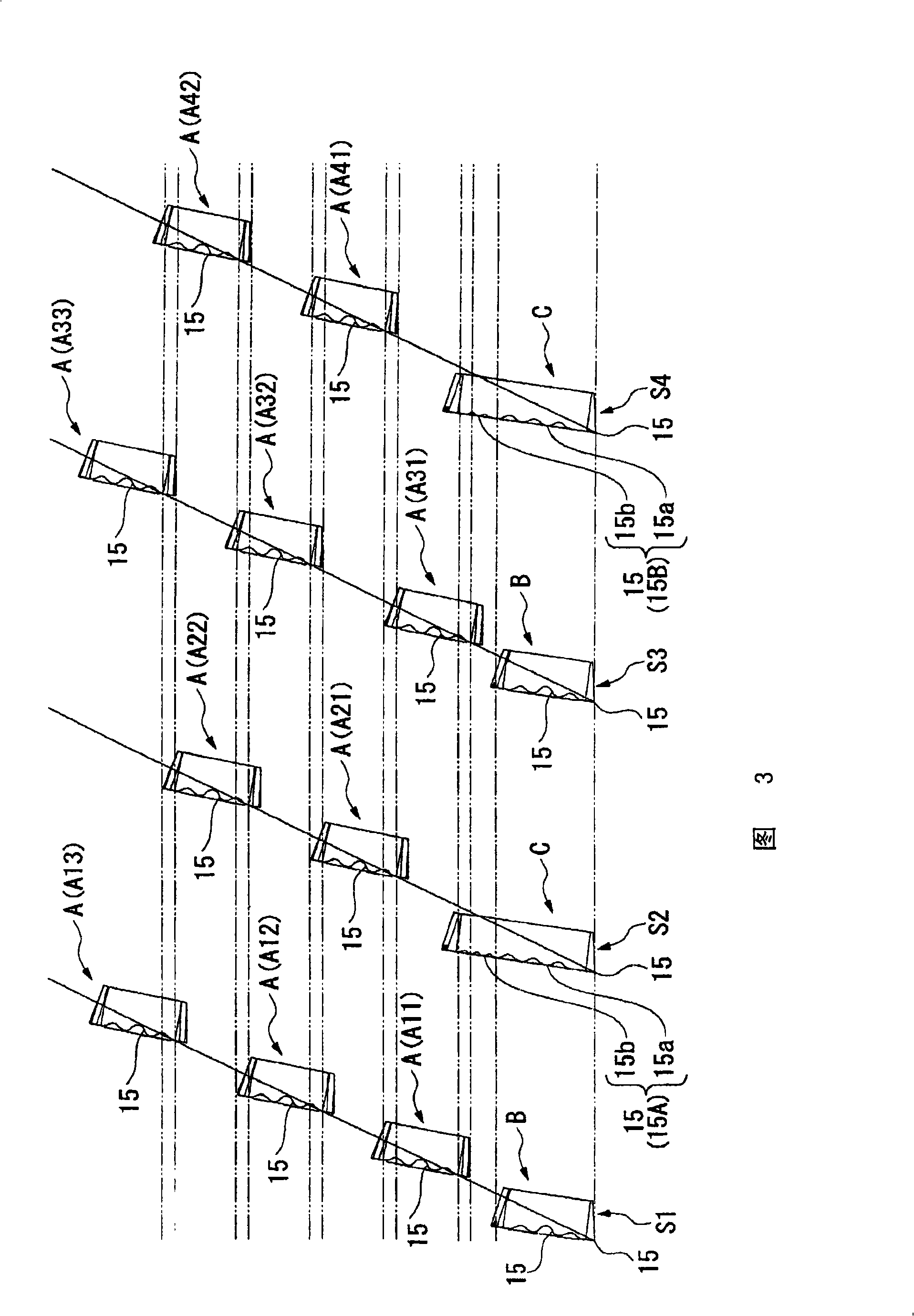
[0062] Figure 1 to Figure 3 One embodiment of the roughing end mill of the present invention is shown. Figure 4 to Figure 8 Blade A shown, Figure 9 to Figure 13 Blade B shown, Figure 14 to Figure 19 The shown insert C is detachably attached to this rough machining end mill, and the insert C is an insert for rough machining according to one embodiment of the present invention. In addition, the other inserts A and B are also inserts for rough machining having wave-shaped cutting edges.

[0063] In the rough machining end mill of this embodiment, the end mill body 1 is formed of steel or the like, and has a substantially cylindrical shape centered on the axis 0. On the outer periphery of the tip part, several lines are formed at equal intervals in the circumferential direction. (Four in this embodiment) Helical chip discharge flutes 2. These chip discharge flutes 2 follow from the front end of the end mill body 1 toward the rear end side in the axis O direction ( figure ...


PUM


Abstract

This roughing end mill is provided with an end mill body which is rotated around an axis, and with a plurality of inserts which are placed on an outer circumference of the end mill body at a predetermined distance apart from each other in the direction of the axis. The plurality of inserts form insert rows of which a plurality are provided in a circumferential direction of the end mill body, and at least the inserts included in a group are positioned so as to be offset in the axial direction from each other in the different insert rows which are mutually adjacent in the circumferential direction. The inserts included in the group are provided with cutting edges which face towards an outer circumferential side of the end mill body and which are formed as waveform cutting edges which undulate as they move in the axial direction. One insert of one insert row of the inserts included in the group and an insert of another insert row which is offset therefrom in the axial direction among the inserts included in the group are positioned such that the waveform cutting edges of each of these inserts make up a waveform cutting edge row whose phase is continuous on a rotation trajectory around the axis. A plurality of these waveform cutting edge rows which have mutually different phases are formed on the outer circumference of the end mill body.

Description

technical field [0001] The present invention relates to a roughing insert provided with a wave-shaped cutting edge for rough machining a workpiece, and an insert detachable roughing end mill having such a roughing insert attached to the outer periphery of an end mill body . [0002] This application claims the priority of Japanese Patent Application No. 2006-248174 filed on September 13, 2006, and Japanese Patent Application No. 2006-295907 filed on October 31, 2006, and the contents thereof are cited here. Background technique [0003] As such a detachable insert-type roughing end mill, for example, Patent Documents 1 and 2 propose a technology in which a plurality of helical grooves are formed on the outer periphery of a cylindrical tool body and spaced in these helical grooves. The blades in the shape of a quadrangular flat plate are attached with a small gap, and the blades of different helical grooves are arranged at approximately equal intervals so as to complement th...

Claims


Application Information

Patent Timeline
Patent Type & Authority Patents(China)
IPC IPC(8): B23C5/10B23C5/20
CPCB23C2200/206B23C2210/66B23C5/207B23C2220/60B23C5/109Y10T407/1942Y10T407/1924Y10T407/192Y10T407/1671Y10T407/195B23C5/202B23C5/205
Inventor 堀池伸和北嶋纯
Owner MITSUBISHI MATERIALS CORP
Why Eureka
Try Eureka