
Automatic warehouse

A technology of automatic warehouse and warehouse, applied in the field of automatic warehouse, to achieve the effect of high degree of freedom and versatility, effective use of factory space, and high storage efficiency

Inactive Publication Date: 2009-08-19
HIRATA & CO LTD
View PDF3 Cites 12 Cited by
  • Summary
  • Abstract
  • Description
  • Claims
  • Application Information

AI Technical Summary

Problems solved by technology

[0013] The present invention solves the above-mentioned problems of the existing automatic warehouse, and its purpose is to provide an automatic warehouse that uses storage shelves with storage shelves. Multiple trolleys, high degree of freedom, high storage efficiency, effective use of factory space, and adaptability to unit production

Method used


Image

  • Automatic warehouse
  • Automatic warehouse
  • Automatic warehouse

Examples


Embodiment

[0061] Next, an example (embodiment 1) of the present invention will be described.

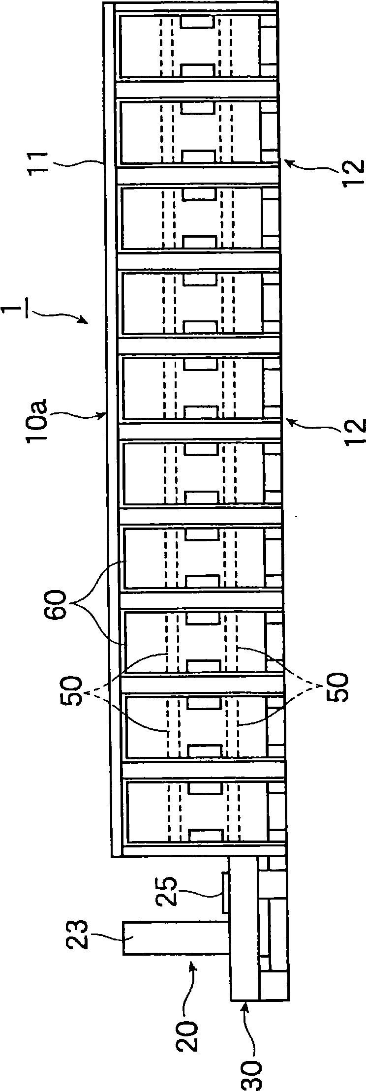
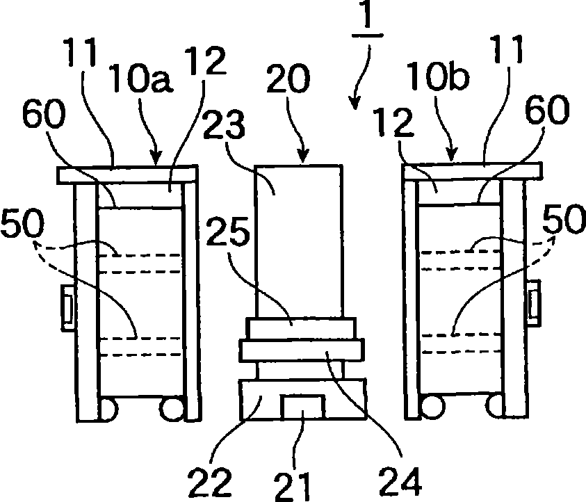
[0062] Figure 1A ~ Figure 1C It is a figure showing the automatic warehouse of this Example 1, Figure 1A is its floor plan, Figure 1B is its front view, Figure 1C is its side view. also, Figure 2A ~ Figure 2C is a diagram showing the trolleys constituting the automatic warehouse, Figure 2A is its floor plan, Figure 2B is its rear view, Figure 2C is its side view.

[0063] The automatic warehouse of the present embodiment 1 is used in manufacturing and assembling factories of various products, especially in factories adopting the cell production method.

[0064] The overall structure of the automatic warehouse 1 of the present embodiment 1 is roughly as follows Figure 1A ~ Figure 1C As shown, a conveying device 20 is arranged between a pair of warehouse units 10a, 10b that are long and facing each other in the horizontal direction, and a plurality of shelves are respectively p...


PUM


Abstract

An automatic warehouse (1) having shelves (50) and a conveyance device (20). The shelves (50) are arranged in the horizontal direction and placed as a single tier shelf or multiple tier shelves, and the shelves (50) individually store objects to be stored. The conveyance device (20) performs delivery and reception between each of shelves (50). All of the multiple shelves (50) have carriages (60) capable of moving between the inside and outside of the automatic warehouse. The carriages (60) function also as storage shelves, so that the automatic warehouse has high degree of freedom and high receiving efficiency. Also, the warehouse enables efficient use of a factory space and is capable of coping with cell production.

Description

technical field [0001] The invention relates to an automatic warehouse, in particular to an automatic warehouse with high degree of freedom, high storage efficiency, effective use of factory space and adaptability to unit production. Background technique [0002] Figure 6A ~ Figure 6C The existing automated warehouse 01 is shown in . here, Figure 6A is the floor plan of the automatic warehouse 01, Figure 6B is its front view, Figure 6C is its right view. [0003] In this automatic warehouse 01, a pair of warehouse units 010a and 010b made up of a plurality of stacked shelves 050 arranged side by side in the horizontal direction are arranged opposite to each other, and a conveyor system consisting of a stacking crane or the like is provided between them. The device 020 transfers stored objects between each shelf 050 and the transfer device 020 . All of the plurality of shelves 050 are configured as fixed shelves, and the transport device 020 holds the stored objects ...

Claims


Application Information

Patent Timeline
Patent Type & Authority Applications(China)
IPC IPC(8): B65G1/04B65G1/10
CPCB65G1/02B65G1/0407
Inventor 橘胜义大畠基裕平泽洋一大久保洋加藤光弘
Owner HIRATA & CO LTD
Learn More