Optical sensor with collision protection for a measurement machine

Active Publication Date: 2012-05-10
LEICA GEOSYSTEMS AG
View PDF8 Cites 10 Cited by
  • Summary
  • Abstract
  • Description
  • Claims
  • Application Information

AI Technical Summary

Benefits of technology

[0028] A defined reference plane may be introduced within the optical sensor for interferometric measurement methods, preferably in the form of a reflection from one of the optics surfaces in order in this way to achieve a short dist

Problems solved by technology

Therefore, the optical sensor has virtually no protection in the event of a collision with the workpiece at

Method used


Image

  • Optical sensor with collision protection for a measurement machine
  • Optical sensor with collision protection for a measurement machine
  • Optical sensor with collision protection for a measurement machine

Examples


Embodiment Construction

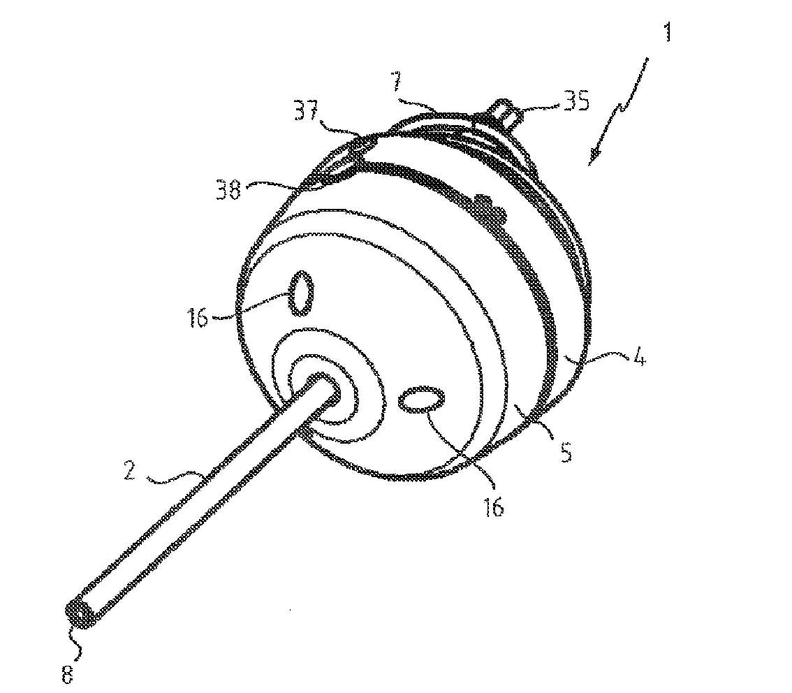
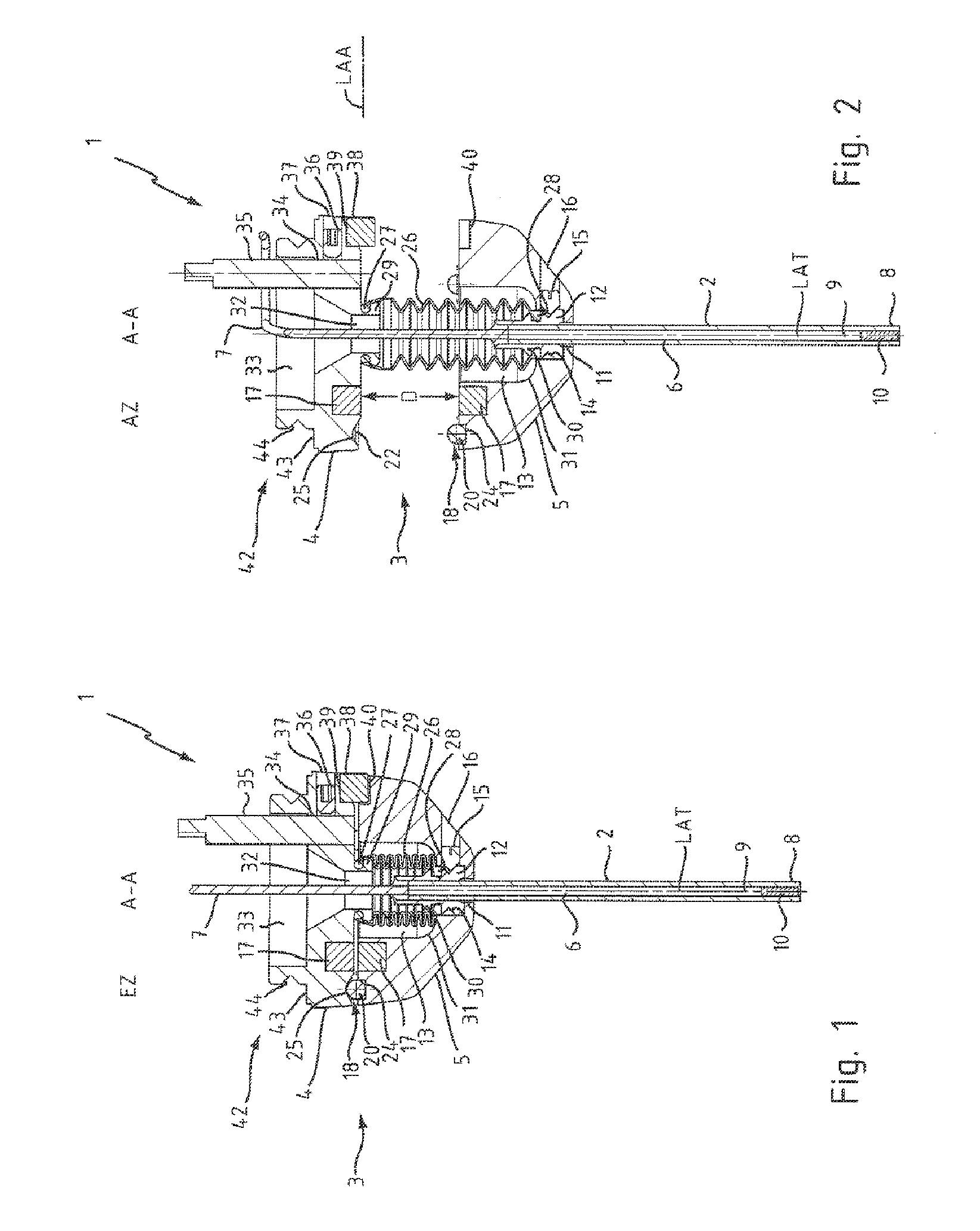
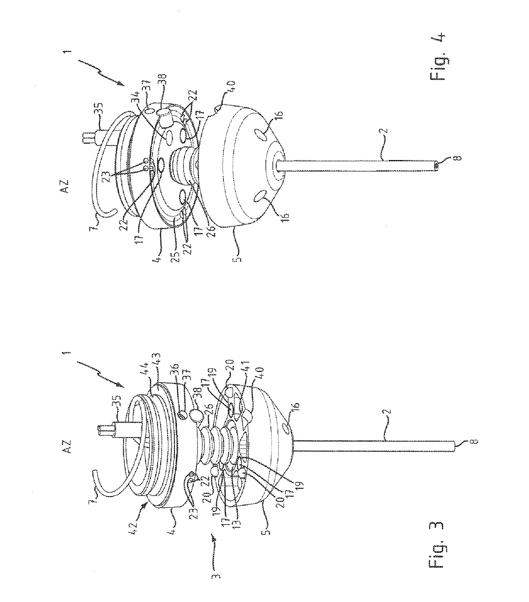
[0039] The sensor element 2 projects through an axial hole 11 into the coupling part 5 on the sensor element side, and is held in a bush 12 in the coupling part 5 on the sensor element side. The bush 12 is arranged in a recess 13 in the coupling part 5 on the sensor element side. The bush 12 has a circumferential triangular notch 14, in which grub screws 15 engage. The grub screws 15 are screwed into three threaded holes 16 in the coupling part 5, which threaded holes 16 are arranged offset through an angle of 120° with respect to one another around the longitudinal axis LAT of the sensor 1.

[0040] Magnets 17 and an isostatic three-point bearing 18 are provided for coupling the coupling part 5 on the sensor element side to the coupling part 4 on the measurement machine side and are arranged on three webs 19 in the coupling part 5 on the sensor element side, which webs 19 are likewise at an angle of 120° with respect to one another around the longitudinal axis LAT of the sensor 1. Cy...


PUM


Abstract

The invention relates to an optical sensor with collision protection for a measurement machine, in particular for a coordinate measurement machine. The optical sensor comprises a sensor-side coupling part for mechanically and optically connecting to the measurement machine, and a sensor element. According to the invention, the sensor comprises a sensor protective coupling as collision protection, said protective coupling comprising a coupling part on the measurement machine side and a coupling part on the sensor element side, wherein a fiber optic cable is routed between the coupling parts of the sensor protective coupling and wherein a fiber optic cable protection element surrounds the fiber optic cable, wherein the ends of the fiber optic cable protection element are fastened to the associated coupling part of the sensor protective coupling.

Description

[0001] The invention relates to an optical sensor with collision protection for a measurement machine, in particular for a coordinate measurement machine, which has a sensor-side coupling part for mechanical and optical connection to the measurement machine and has a sensor element. BACKGROUND [0002] It is known in the prior art for tactile, but not optical, sensors for coordinate measurement machines to be equipped with collision protection. By way of example, EP 0 426 492 A2 discloses a tactile sensor which is intended for continuous measurement of workpieces and has a sensor element which is held in an equilibrium position by restoring forces. The restoring forces are produced by springs. The sensor element is held, preferably magnetically, on a sensor holder via precision bearings, with the restoring forces acting on the sensor holder. [0003] In contrast to this tactile sensor, an optical sensor is moved past the surface of a workpiece to be measured, without touching it. There ...

Claims


Application Information

Patent Timeline
IPC IPC(8): G01B5/004
CPCG01B11/007
Inventor JENSEN, THOMASSAUPE, FRANKVULLIOUD, BENJAMIN
Owner LEICA GEOSYSTEMS AG
Why Eureka
Try Eureka