Common-path frequency-scanning interferometer

a frequency-scanning interferometer and common-path technology, applied in the field of wavelengthscanning interferometry or multi-wavelength interferometry, can solve the problems of difficult adaptation to phase shifting, difficult to adapt to common-path frequency-scanning interferometers, and difficulty in reducing the sensitivity of environmental effects, so as to reduce the dispersion, minimize the influence of disturbance, and reduce the sensitivity to environmental effects

Active Publication Date: 2006-10-31
LIGHTGAGE
View PDF25 Cites 6 Cited by
  • Summary
  • Abstract
  • Description
  • Claims
  • Application Information

AI Technical Summary

Benefits of technology

[0034]The invention extends frequency-scanning interferometry to common-path interferometric systems. The advantages of common-path interferometric systems for reducing sensitivity to environmental effects, such as vibrations and air turbulence, and for reducing dispersion caused by separate optical components along different object and reference beam paths are preserved while a measurement range (i.e., an unambiguous measuring interval) can be expanded.
[0035]In accordance with the invention, phase-shifting actuators and techniques are unnecessary to resolve measuring ambiguities. A reference element unencumbered by phase-shifting requirements can be arranged to incorporate the functions o

Problems solved by technology

Although phase shifting is routinely used for resolving interference ambiguities, the practice requires additional measurements, complicates measuring apparatus, and consumes processing time.
Common-path interferometric systems, such as Fizeau interferometers, are not easily adaptable to phase shiftin

Method used


Image

  • Common-path frequency-scanning interferometer
  • Common-path frequency-scanning interferometer
  • Common-path frequency-scanning interferometer

Examples


Embodiment Construction

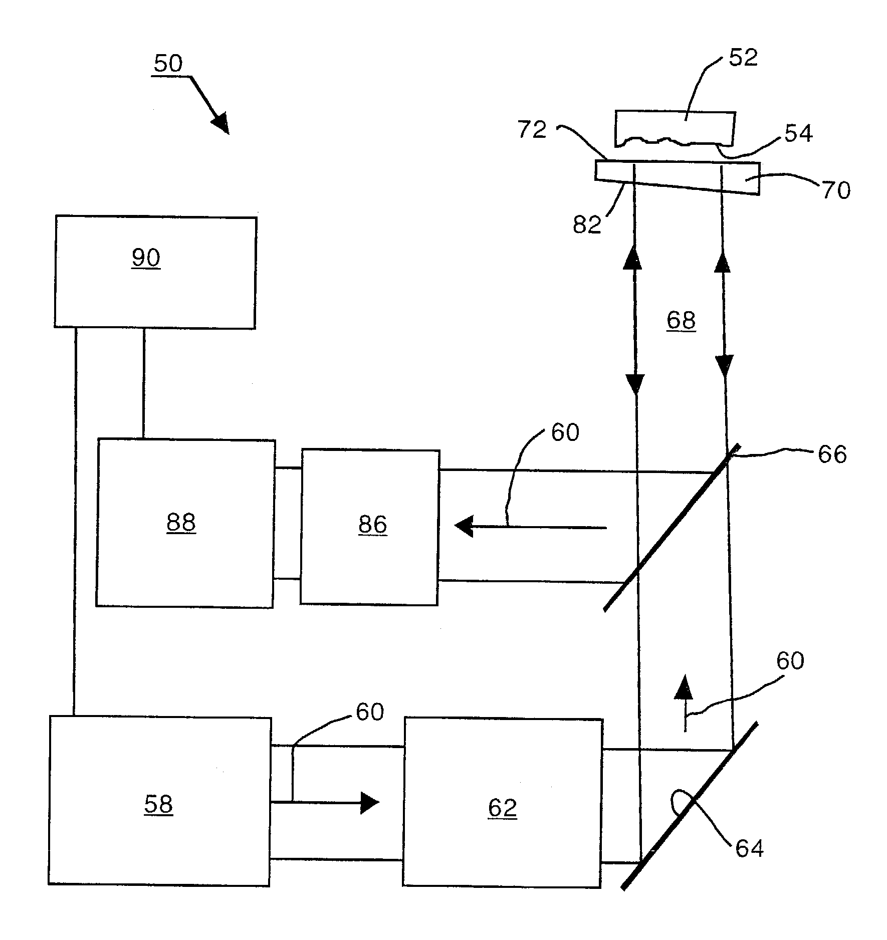
[0064]As shown in FIG. 3, an exemplary frequency-scanning interferometer 50 is arranged in accordance with the invention as a common-path (e.g., Fizeau) interferometer for measuring topographical features of a test object 52. A radiation source 58 produces a measuring beam 60 for acquiring information about a test surface 54 on the test object 52. Preferably, the radiation source 58 is a source of coherent radiation, such as a diode laser (e.g., a GaAs-based laser), tunable through a limited range of frequencies (or wavelengths). A choice of nominal wavelength (e.g., 780 nm) can be made within the visible or invisible spectrum and can be selected on such bases as cost, resolution, and reflectance of the test object An exemplary frequency-tunable laser preferred for the practice of this invention is disclosed in copending U.S. application Ser. No. 10 / 446,012, filed 27 May 2003, entitled TUNABLE LASER SYSTEM HAVING AN ADJUSTABLE EXTERNAL CAVITY, now U.S. Pat. No. 6,690,690, which is h...


PUM


Abstract

Frequency-scanning interferometry is applied to common-path interferometers for measuring topographical features of test objects. A reference element located adjacent to a test object functions as both a beamsplitter and a reference surface. A first portion of a measuring beam reflects from the reference surface of the reference element as a reference beam, and a second portion of the measuring beam transmits through the reference element to and from a surface of the test object as an object beam. Both beams are conveyed along a common path to a detector that records a plurality of intensity variations produced by constructive and destructive interference between localized portions of the object and reference beams associated with different transverse coordinates on the test object surface. An illumination frequency of the measuring beam is incrementally modified through a range of different frequencies sufficient to alternate the intensity variations between conditions of constructive and destructive interference, which occur at modulation frequencies sensitive to path length differences between corresponding points on the surfaces of the test object and reference element.

Description

RELATED APPLICATIONS [0001]This application claims the benefit of prior filed U.S. Provisional Application No. 60 / 390,970, filed 24 Jun. 2002, which is hereby incorporated by reference.TECHNICAL FIELD [0002]Frequency-scanning interferometry, also referred to as wavelength-scanning interferometry or multi-wavelength interferometry, generates a succession of interference patterns at different frequencies of illumination and evaluates the patterns to provide profile measurements of test objects.BACKGROUND [0003]The development of frequency-scanning interferometers that use multiple laser frequencies, or wavelengths, to perform measurements has been underway for several years. The interferometers are especially useful for measuring surface profiles of test objects as measures of surface variations taken normal to a reference plane or surface. References exemplifying this development include:[0004]R. G. Pilston and G. N. Steinberg, “Multiple-Wavelength Interferometry with Tunable Source,...

Claims


Application Information

Patent Timeline
IPC IPC(8): G01B11/02G01B9/02G01B11/24
CPCG01B11/2441G01B9/02004G01B9/02059G01B9/02057G01B9/02078
Inventor MARRON, JOSEPH C.
Owner LIGHTGAGE
Why Eureka
Try Eureka