Ceramic film filtering element

A filter element and ceramic membrane technology, which is applied in the structural field of ceramic membrane filter elements, can solve problems such as complex processing technology and large liquid penetration resistance, and achieve the effects of reducing production costs, simplifying the manufacturing process, and reducing difficulty

Inactive Publication Date: 2006-07-26
JIANGSU JIUWU HITECH
View PDF2 Cites 10 Cited by
  • Summary
  • Abstract
  • Description
  • Claims
  • Application Information

AI Technical Summary

Problems solved by technology

The disadvantage of ceramic membrane elements is that the liquid penetration resistance of the multi-channel structure is relatively large
[0005] The structure of the ceramic support body in U.S. Patent Nos. 5,009,781 and 5,108,601 is honeycomb, and it has a lot of channels. In order to reduce the penetration resistance, it must open a lot of grooves to guide the flow, collect the permeate into the drainage groove, and pass through the drainage groove. Holes or grooves are made on the outside for drainage, or a hole is opened in the center of the support to connect a drainage tube for drainage, so the processing technology is complicated

Method used


Image

  • Ceramic film filtering element
  • Ceramic film filtering element
  • Ceramic film filtering element

Examples


Embodiment 1

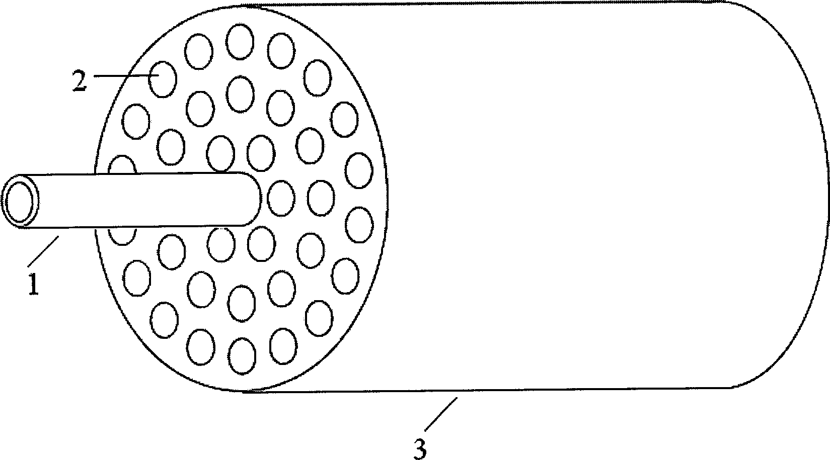
[0028] The shape of the multi-channel membrane tube is as follows figure 1 shown. The membrane tube is extruded, with a length of 1m and a diameter of 41mm. There are 37 channels inside. The diameter of the channel is 4mm, and the wall thickness between the channels is 2mm. The resin glue is sealed and the other end is sealed. Prepare a layer of aluminum oxide membrane by soaking slurry coating, the average pore size of the membrane is 0.2μm, the porosity of the support and the membrane is 35%, it is operated under the pressure of 0.1MPa, and the pure water flux is 1000L / m 2 h.

Embodiment 2

[0030] The shape of the multi-channel membrane tube is as follows figure 1 shown. The membrane tube is extruded, with a length of 1m and a diameter of 41mm. There are 37 channels inside. The diameter of the channel is 4mm, and the wall thickness between the channels is 2mm. The resin glue is sealed and the other end is sealed. Prepare a layer of aluminum oxide membrane by soaking slurry coating, the average pore size of the membrane is 0.5μm, the porosity of the support and the membrane is 35%, it is operated under the pressure of 0.1MPa, and the pure water flux is 2000L / m 2 h.

Embodiment 3

[0032] The shape of the honeycomb ceramic membrane tube is as follows: Figure 5 shown. The membrane tube is extruded, with a length of 1m and a diameter of 41mm. There are 59 channels inside. The side length of the channel is 2.5mm, and the wall thickness between the channels is 1.2mm. The two ends of the central channel of the membrane tube are connected to each other. Drainage tube, sealed with polyurethane glue. Prepare a layer of zirconia membrane by soaking slurry coating, the average pore size of the membrane is 0.2μm, the porosity of the support and the membrane is 35%, it is operated under the pressure of 0.1MPa, and the pure water flux is 800L / m 2 h.


PUM


Abstract

The invention relates a ceramics film filtration element. The center hole of ceramics film tube is uncoated. At the center hole there is draught tube, and the gap between center hole and draught tube is sealed by epoxide resin to prevent the permeable liquid and raw liquid from mixing. The invention predigests the manufacturing technique and reduces the cost.

Description

technical field [0001] The invention relates to a structure of a ceramic membrane filter element, which is characterized by a short path for permeable liquid to pass through the element. Background technique [0002] The membrane separation process of microfiltration and ultrafiltration is used to separate liquids containing dissolved solutes or suspended particles, in which solvents and solute small molecules pass through the membrane, and solute macromolecules and suspended particles are retained by the membrane. [0003] The core part of the membrane filtration device is the filter membrane. Compared with the organic membrane, the ceramic membrane has the advantages of good chemical stability, high mechanical strength, strong anti-microbial ability, high temperature resistance, narrow pore size distribution, and high separation efficiency. [0004] The ceramic membrane elements commonly used in the industry are mainly in the form of multi-channel, because the filter eleme...

Claims


Application Information

Patent Timeline
Patent Type & Authority Applications(China)
IPC IPC(8): B01D63/06B01D29/31B01D71/02
Inventor 徐南平范益群漆虹
Owner JIANGSU JIUWU HITECH
Why Eureka
Try Eureka