
Shuttle type magnetic refrigerator

A magnetic refrigerator, reciprocating technology, applied in refrigerators, refrigeration and liquefaction, machines using electric/magnetic effects, etc., can solve problems such as performance degradation, and achieve the effect of preventing deformation

Inactive Publication Date: 2011-01-12
DAEWOO ELECTRONICS CO LTD
View PDF1 Cites 0 Cited by
  • Summary
  • Abstract
  • Description
  • Claims
  • Application Information

AI Technical Summary

Problems solved by technology

Therefore, the conventional active magnetic cold accumulator cannot solve its original purpose, such as being used in an air conditioner, since the initial temperature of the heat transfer fluid flowing from the hot end to the cold end is eliminated, causing its performance to drop

Method used


Image

  • Shuttle type magnetic refrigerator
  • Shuttle type magnetic refrigerator
  • Shuttle type magnetic refrigerator

Examples


Embodiment Construction

[0047] The above and other objects of the present invention, as well as features and advantages of the present invention will be described in detail below with reference to the accompanying drawings.

[0048] attached Figure 4 and 5 A perspective view and a plan view, respectively, show a preferred embodiment of the reciprocating cold accumulator of the present invention. attached Image 6 shows the attached Figure 4 An exploded perspective view of the main parts of the AMR shown, with Figure 7-14 The cycle of the magnetic refrigerator is shown.

[0049] as attached Figure 4-16 As shown, a magnetic refrigerator according to a preferred solution of the present invention includes a regenerator 100 , a cold-end heat exchanger 160 and a hot-end heat exchanger 170 thermally connected to the regenerator 100 . The cold end heat exchanger 160 is used for cooling, and the hot end heat exchanger 170 is used for heat dissipation.

[0050] as attached Figure 4-6 As shown, the...


PUM


Abstract

The present invention relates to a shuttle type magnetic refrigerator wherein a cold-side heat exchanger 160 is thermally coupled between a far-side inlet / outlet of a first AMR bed and a far-side inlet / outlet of a second AMR bed.

Description

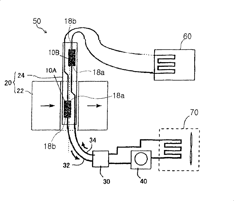
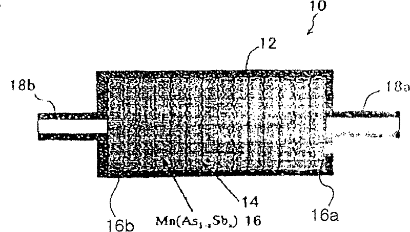
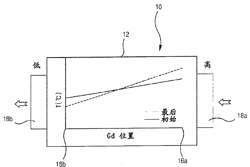
technical field [0001] The invention relates to a reciprocating magnetic refrigerator. Background technique [0002] US Patent No. 6,826,915 discloses a conventional active magnetic regenerator. as attached figure 1 and 2 As shown, according to a conventional active magnetic regenerator including the cycle described above, the temperature of the heat transfer fluid heated in the magnetic field in the first AMR bed 10A is lowered to atmospheric temperature through the hot end heat exchanger 70, and then A heat transfer fluid is passed through the second AMR bed 10B. Meanwhile, because the second AMR bed 10B is located outside the magnetic field, the magnetic refrigeration material layer 16 has a low temperature, and the temperature of the heat transfer fluid decreases when passing through the magnetic refrigeration material layer 16 . The heat transfer fluid having a low temperature passes through the cold end heat exchanger 60 and then enters the first AMR bed 10A to be ...

Claims


Application Information

Patent Timeline
Patent Type & Authority Patents(China)
IPC IPC(8): F25B21/00
CPCY02B30/66Y02B30/00F25B21/00F25B2321/0021
Inventor 李东绾申承
Owner DAEWOO ELECTRONICS CO LTD
Learn More