Supercharge Your Innovation With Domain-Expert AI Agents!

Bimetal charging barrel and manufacturing method thereof

A bimetal and barrel technology is applied in the field of bimetal barrels and their production, which can solve the problems of material waste and complicated barrel process, and achieve the effect of simple process and material saving.

Inactive Publication Date: 2013-08-07
蔡雅芝
View PDF5 Cites 0 Cited by
  • Summary
  • Abstract
  • Description
  • Claims
  • Application Information

AI Technical Summary

Problems solved by technology

[0003] The technical problem to be solved by the present invention is to provide a bimetallic barrel and its manufacturing method, aiming at solving the problem of complex process and material waste of ordinary barrels in the prior art.

Method used


Image

  • Bimetal charging barrel and manufacturing method thereof
  • Bimetal charging barrel and manufacturing method thereof
  • Bimetal charging barrel and manufacturing method thereof

Examples


Embodiment 1

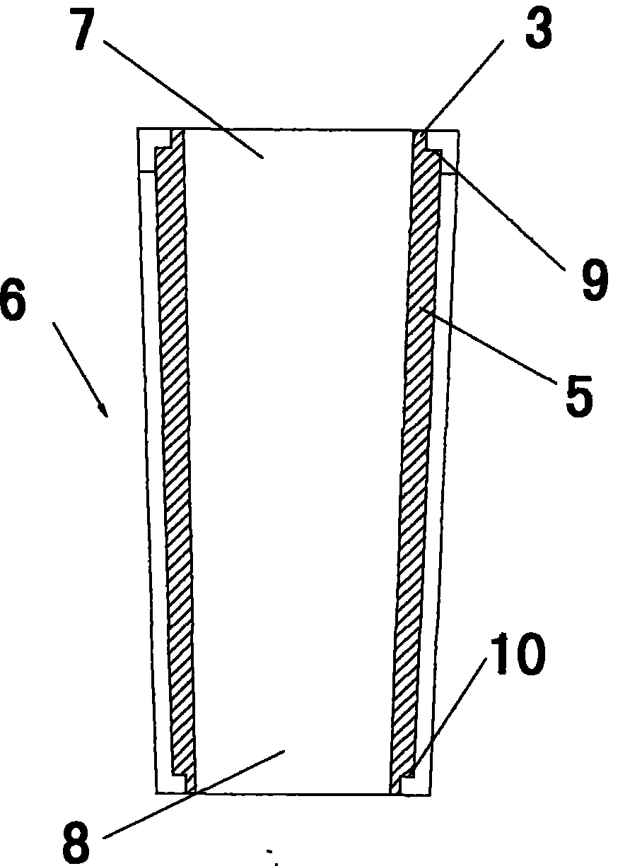
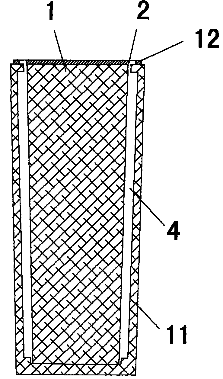
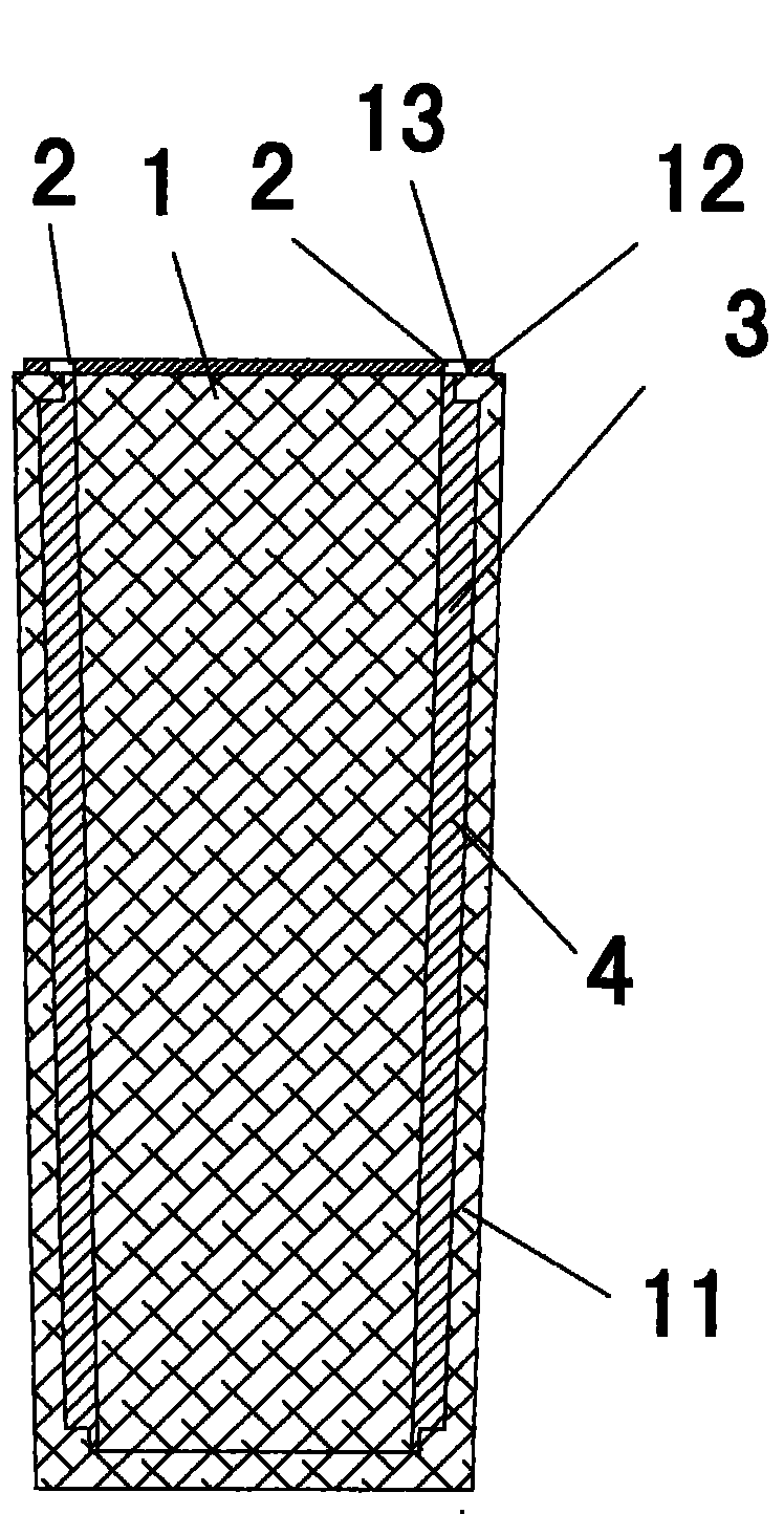
[0037] The bimetal barrel of this specific embodiment, such as figure 1 As shown, the alloy layer 3 and the barrel 6 are included. The structure of barrel 6 is as Figure 5 As shown, it includes an upper barrel 7 and a lower barrel 8 . The upper barrel 7 has an upper groove 9, and the lower barrel 8 has a lower groove 10. The upper barrel 7 and the lower barrel 8 are matched together to form a barrel groove that is only provided in the middle. And the barrel groove does not penetrate to the barrel 6 at both ends of the barrel. The structure of the alloy layer 3 is as Figure 4 As shown, the alloy layer 3 is only provided with a protrusion 5 in the middle, and the protrusion 5 does not extend to both ends of the alloy layer 3 . In the assembly process, the alloy layer 3 is first put into the lower barrel 8, and then the upper barrel 7 is fixed on the lower barrel 8 by screws or glued. After the alloy layer 3 is matched and assembled with the barrel 6 , the protrusion 5 is ...

Embodiment 2

[0047] The bimetal barrel of this embodiment, the steps of its manufacturing method are the same as the steps in Embodiment 1, the difference is that the structure of the mold core 1 of the mold used in the manufacture is different, such as Figure 10 As shown, it is a perspective view of the mold core 1 of this specific embodiment. The cross section of the mold core 1 in Example 1 is a double-hole structure in the shape of an "8", so the specific embodiment of this specific embodiment is made by the mold in this specific embodiment. The difference between the bimetallic barrel and the bimetallic barrel in Example 1 is that the inner wall of the alloy layer 3 has a double-hole structure in the shape of an "8", and the three-dimensional view of the alloy layer in this specific embodiment is as follows Figure 11 shown.

Embodiment 3

[0049]The steps of the manufacturing method of the bimetallic barrel of this specific embodiment are the same as those in the specific embodiment 1, the difference is that, as Figure 12 As shown, the protrusions 5 of the alloy layer 3 are arranged in four at equal intervals.


PUM


Abstract

The present invention discloses a bimetal charging barrel and a manufacturing method thereof. The bimetal charging barrel comprises an alloy layer (3) and a charging barrel (6). The invention is characterized in that the charging barrel (6) comprises an upper charging barrel (7) and a lower charging barrel (8). The upper charging barrel (7) is provided with an upper groove (9). The lower chargingbarrel (8) is provided with a lower groove (10). The upper charging barrel (7) and the lower charging barrel (8) form a charging barrel groove which is only provided at the middle part after matchingtogether. Furthermore the charging barrel groove does not penetrate to the charging barrel (6) at two ends of charging barrel. The alloy layer (3) is only provided with a projection (5) at the middlepart. Furthermore the projection (5) does not extend to two ends of alloy layer (3). The projection (5) is just inserted to the charging barrel groove which is formed by the upper groove (9) and the lower groove (10) through a matching mode. The bimetal charging barrel and manufacturing method according to the invention have the advantages of simple process and material saving.

Description

technical field [0001] The invention relates to the field of financial material barrels, in particular to a bimetallic material barrel and a manufacturing method thereof. Background technique [0002] At present, the barrel is an important part of the plastic plasticizing device. In order to improve the service life and carrying capacity of the barrel, save raw materials and energy consumption. A bimetallic barrel has been proposed. In the previous operation, this layer of alloy was compounded in the ordinary nitride barrel by centrifugal casting method. The so-called centrifugal casting method is to process the ordinary barrel first, then add alloy powder in the barrel, and then Seal the two ends with a cover and heat to melt the alloy powder into a liquid, then place the barrel flat on the roller, and let the barrel rotate around its axis under the drive of the roller, so that the liquid alloy in the body will generate centrifugal force and attach to the barrel On the in...

Claims


Application Information

Patent Timeline
Patent Type & Authority Patents(China)
IPC IPC(8): B29C45/62B29C47/66B22D25/00
CPCB29C47/0849B29C47/661B29C47/662B29C48/682B29C48/6803B29C48/681
Inventor 蔡雅芝
Owner 蔡雅芝
Features
  • R&D
  • Intellectual Property
  • Life Sciences
  • Materials
  • Tech Scout
  • Unparalleled Data Quality
  • Higher Quality Content
  • 60% Fewer Hallucinations
Learn More