
Range hood with smoke deflector

A technology of range hoods and smoke deflectors, which is applied in the direction of removing oil fume, removing smoke dust, and increasing household heat, etc. It can solve problems such as difficult design, unfavorable flow of high-temperature oil fume, and affect the mood of users, so as to achieve the effect of uniform flow

Active Publication Date: 2012-11-21
NINGBO FOTILE KITCHEN WARE CO LTD
View PDF1 Cites 24 Cited by
  • Summary
  • Abstract
  • Description
  • Claims
  • Application Information

AI Technical Summary

Problems solved by technology

Although this patent has improved the smoke exhaust efficiency to a certain extent, there are still deficiencies: one is that the oil fume inlet channel is around the deflector, and the fan is located in the middle of the rear of the deflector, so the stroke of the oil fume is required. First bypass the deflector, and then bend to the middle, causing the four directions of oil fumes to easily interfere with each other near the fan, which on the one hand leads to a significant increase in noise, and on the other hand also affects the actual smoke exhaust efficiency; secondly, because of the deflector Surroundings are suspended, and oil droplets will inevitably form on the back of the deflector and drip down along the deflector, which will seriously affect the user's mood, and it also appears quite unhygienic, so the lower edge of the deflector It needs to be overlapped on the inner side of a baffle plate. In this way, on the one hand, the overall appearance of the range hood looks very uneven; Then fold down, and then fold up from the lower end edge of the deflector to the air suction port, so that the oil fume flow path of this part becomes very tortuous, especially a section that is bent downward, which is very unfavorable for the flow of high-temperature oil fume, so It affects the actual smoke exhaust efficiency; moreover, the degree of divergence of the oil fume in the lower part is relatively low, and it is relatively concentrated, so the lower smoke guide port is a very important smoke exhaust channel. Obviously, the design of the above-mentioned bent shape oil smoke channel is difficult to achieve. Satisfactory effect

Method used


Image

  • Range hood with smoke deflector
  • Range hood with smoke deflector

Examples


Embodiment

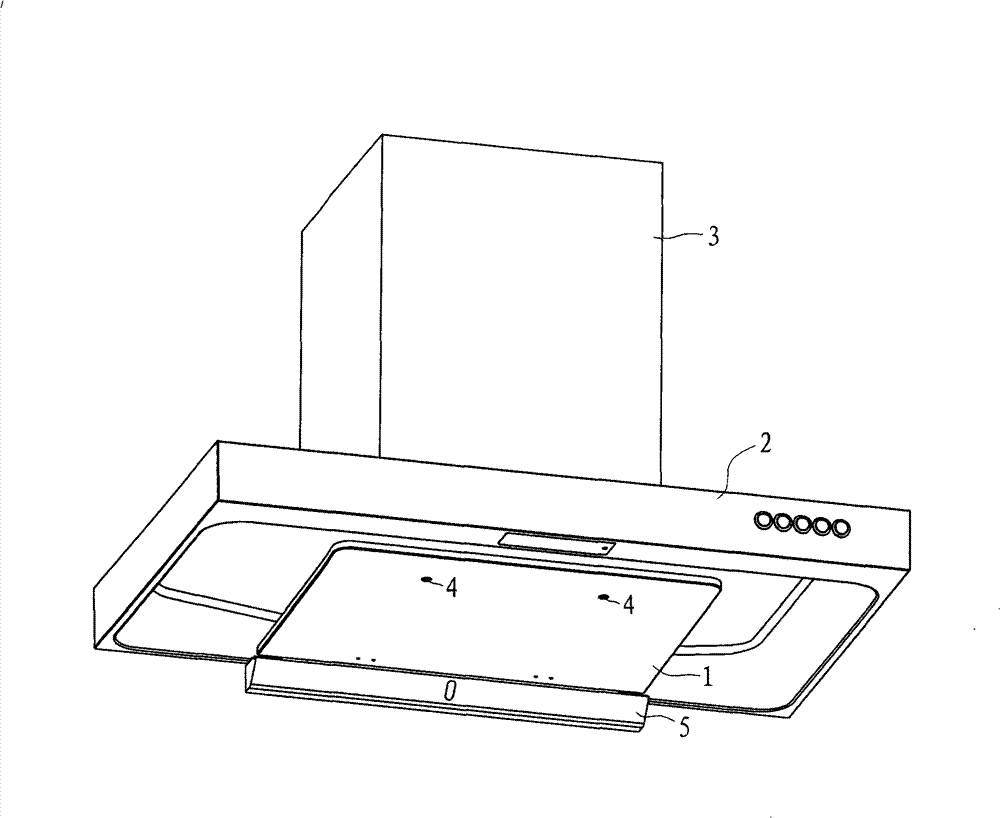
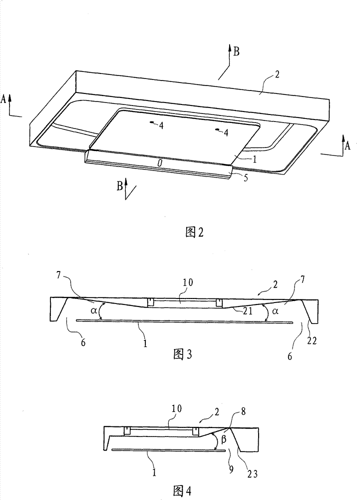
[0018] Example: Reference figure 1 and figure 2 , this embodiment includes a smoke guide plate 1, a smoke collection hood 2 and a body 3. The smoke guide plate 1 is horizontal and has an oil collection groove 5 on the inner side. The smoke guide plate 1 is arranged on the air inlet of the smoke collection hood 2 through two bolts 4. On the end face, the smoke collecting hood 2 has a central air inlet 10 (such as image 3 and Figure 4 Shown), the body 33 has a fan and has an air outlet.

[0019] Such as image 3 and Figure 4 As shown, the front end and the two sides of the end surface of the air inlet of the smoke collecting hood 2 protrude to form the front peripheral part 23 and the side peripheral part 22 respectively, and the middle part is concave to form the air inlet part 21 . The air inlet portion 21 smoothly transitions from the edge to the middle and gradually protrudes downwards until reaching the air inlet 10 of the smoke collecting hood.

[0020] The front...


PUM


Abstract

A range hood with a smoke deflector, comprises a body, a smoke collecting cover and the smoke deflector, wherein an air inlet is arranged on the smoke collecting cover, the smoke deflector faces to the air inlet and be in the predetermined distance from the smoke collecting cover, thus a oil smoke channel through which the oil smoke can pass is formed between the smoke deflector and the smoke collecting cover, the range hood is characterized in that the distance between the smoke deflector corresponding to the oil smoke channel and the smoke collecting cover is gradually reduced from the periphery of the smoke deflector to the air inlet. Compared with the prior art, the invention has the advantages: the smoke deflector is used for forming the wall-attachment effect, the oil smoke flow uniformly without series flow, the distance between the smoke deflector and the smoke collecting cover is gradually reduced from the periphery of the smoke deflector to the air inlet, so that the Venturieffect is formed conveniently, thus accelerating the sucking of smoke by the blower fan.

Description

technical field [0001] The invention relates to a device for removing smoke from cooking in a kitchen, in particular to a range hood with a smoke guiding plate. Background technique [0002] Chinese utility model patent ZL00263535.6 "full-circumferential deflector for range hood" has improved the traditional range hood. An air suction port and an air outlet are provided at the position, and a deflector is provided on the end side of the air suction port of the casing, and a predetermined distance is maintained between the deflector and the suction port. There is also a predetermined distance between the perimeters, and a full-circumferential smoke guide is formed, so that when the fan is running, the oil smoke can be sucked and discharged by the smoke guides around the deflector. Although this patent has improved the smoke exhaust efficiency to a certain extent, there are still deficiencies: one is that the oil fume inlet channel is around the deflector, and the fan is loca...

Claims


Application Information

Patent Timeline
Patent Type & Authority Patents(China)
IPC IPC(8): F24C15/20
CPCB08B15/02
Inventor 李斌董一龙赵沛彪茅忠群诸永定曹亚裙
Owner NINGBO FOTILE KITCHEN WARE CO LTD
Learn More