
Method for calibrating micro thrust

A calibration method and thrust technology, which is applied in the measurement of elastic deformation force by measuring gauges, etc., can solve problems such as the problem of affecting the accurate measurement of micro thrust calibration, and achieve the effect of simple control and use and easy to master.

Inactive Publication Date: 2009-08-26
BEIHANG UNIV
View PDF1 Cites 15 Cited by
  • Summary
  • Abstract
  • Description
  • Claims
  • Application Information

AI Technical Summary

Problems solved by technology

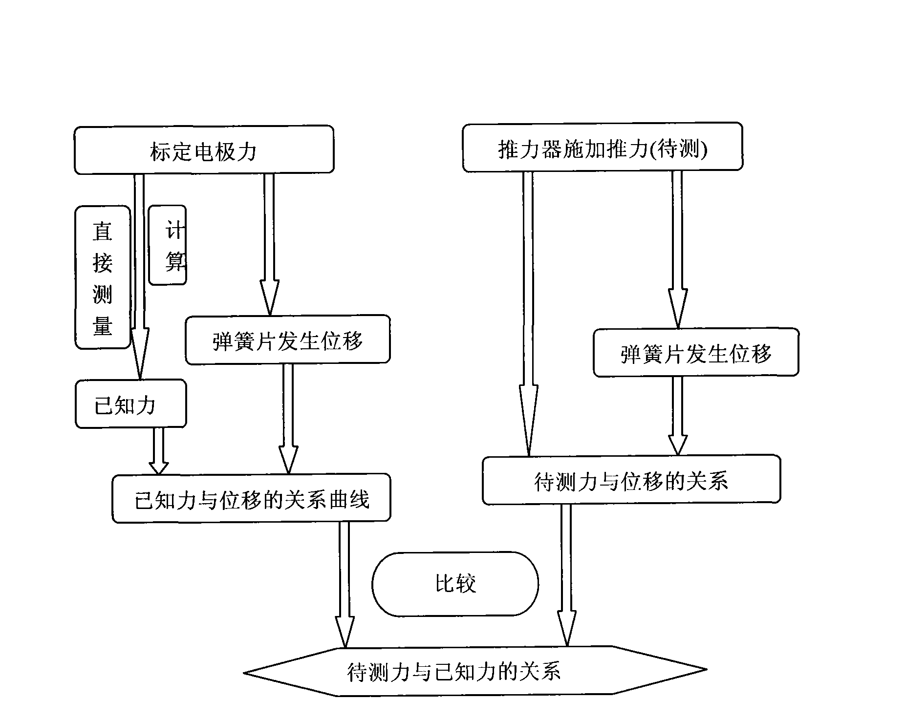
[0009] The purpose of the present invention is to provide a calibration method for micro-thrust. Aiming at the problems of current domestic micro-North-level thrust measuring devices, mainly the connection of supporting elements and accessories affects the accurate measurement of micro-thrust and the calibration of micro-thrust. As the key elastic sensitive element, the steady-state micro-thrust of the micro-thrust engine can be measured more accurately through the conversion of displacement and the method of electrostatic force calibration. The thrust measurement range is 0-500μN

Method used


Image

  • Method for calibrating micro thrust
  • Method for calibrating micro thrust
  • Method for calibrating micro thrust

Examples


Embodiment Construction

[0042] The technical solutions of the present invention will be further described below in conjunction with the accompanying drawings and embodiments.

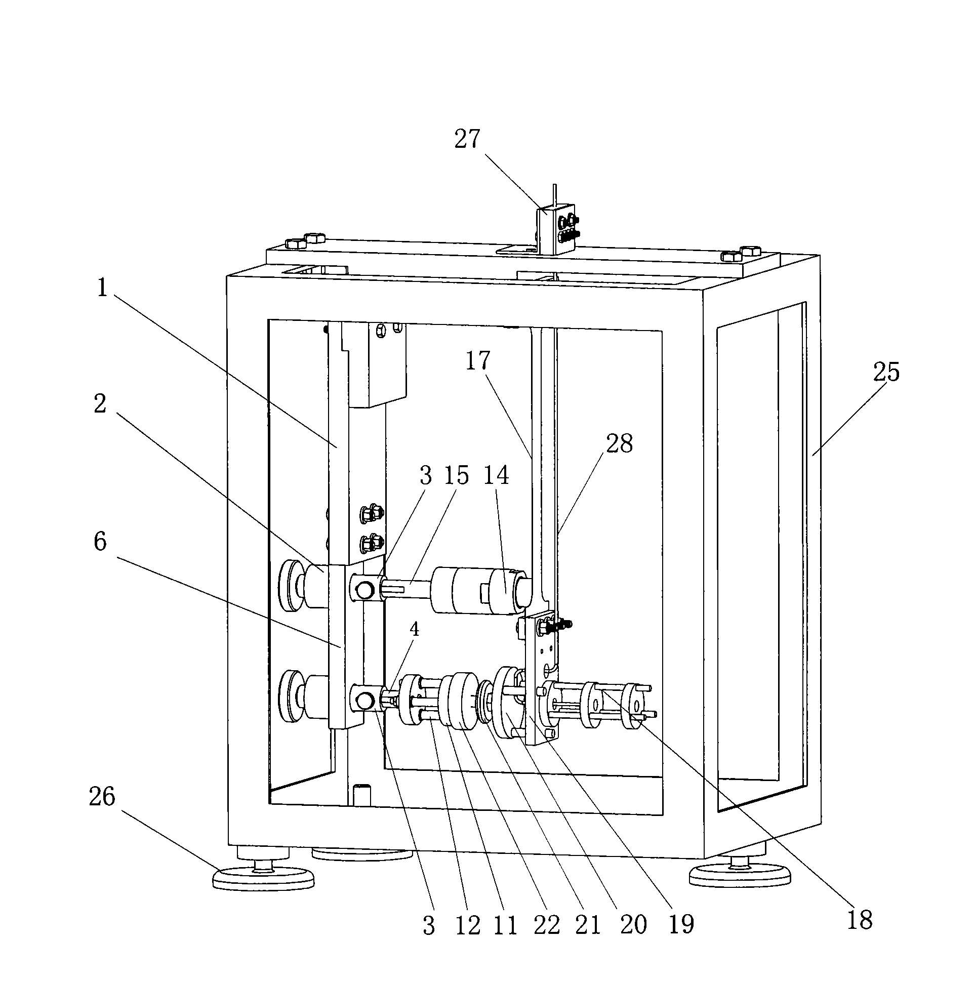
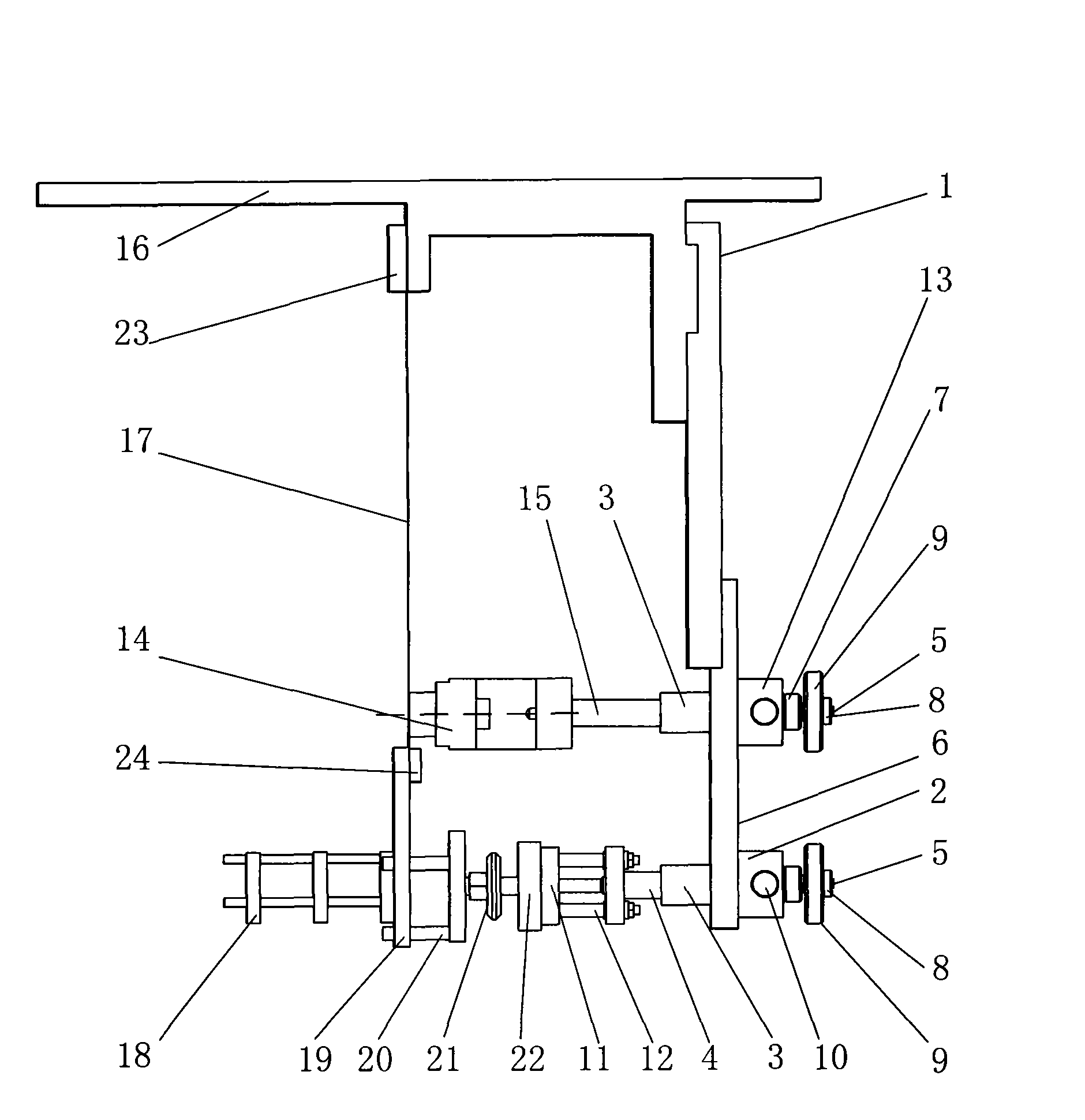
[0043] Such as figure 2 , 3 As shown, the hardware device applied by the method of the present invention is installed:

[0044] (1), first install the adjustment bracket 26 on the thrust frame frame 25, then install the main beam 16 on the thrust frame frame 25, then install the lateral movement seat 1 on the main beam 16, and then fix the longitudinal movement seat 6 On the lateral moving seat 1 , the electrode seat 2 and the sensor seat 13 are welded on the longitudinal moving seat 6 .

[0045] (2) Assemble the fixed shaft 3, the adjusting screw rod 5, the washer end cover 7, the lock nut 8, the handle 9, and the moving long shaft 15 into one, and then fix it on the sensor seat 13 with the fixing screw 10.

[0046] (3) Assemble the fixed shaft 3 moving shaft 4 adjusting screw rod 5 washer end cover 7 locking nut 8 handle...


PUM


Abstract

A method for calibrating micro thrust is characterized in that the method specifically comprises the following steps: (1) adjusting a thrust stand frame to be horizontal by an adjusting bracket and aligning the anode of a calibration electrode with the cathode thereof in parallel by adjusting balance weight and a fixed plate below a spring piece; (2) adjusting the distance between the anode and the cathode of the calibration electrode and the distance between a displacement sensor and the spring piece to facilitate the displacement sensor and the calibration electrode to work in an effective range; (3)applying voltage to the calibration electrode for calibration to obtain the electrostatic force, voltage and displacement calibration curve; (4) switching off the powder supply on the calibration electrode and apply voltage to a thruster to obtain the flow, extracting voltage and displacement curve and then obtain the flow, extracting voltage and thrust curve by calibrating curve.

Description

Technical field: [0001] The invention relates to a micro-thrust calibration method, which belongs to the technical field of space micro-thrust engines. Background technique: [0002] Space micro-thrust engine technologies such as micro-propulsion and electric propulsion are widely used in many fields such as aerospace. Micro-thrust measurement is a key technology in engine ground tests. Only when the measured thrust is obtained can the actual performance parameters of the engine be obtained ( The actual specific impulse of the engine), and carry out further design and development work. [0003] Since the thrust of the micro-thrust engine is very small (mN level or μN level), the connection of the propellant gas circuit and the circuit has a great influence on the thrust measurement, and the whole engine must work in a vacuum, so the thrust Direct measurement poses great difficulties. [0004] For the measurement of the tiny thrust of the engine, according to the different ...

Claims


Application Information

Patent Timeline
IPC IPC(8): G01L1/04
Inventor 王安良汤海滨胡晓亮钟凌伟
Owner BEIHANG UNIV
Learn More