Passive clamping single-phase single-grade bridge type power factor correcting convertor and control method thereof

A power factor correction and converter technology, applied in the direction of AC power input conversion to DC power output, output power conversion device, high-efficiency power electronic conversion, etc., can solve the problem of slow circuit response speed, transformer voltage peak, output side power frequency, etc. Ripple and other problems, to eliminate voltage spikes, reduce the capacity level, to achieve the effect of power factor correction

Inactive Publication Date: 2009-08-26
HARBIN INST OF TECH
View PDF0 Cites 11 Cited by
  • Summary
  • Abstract
  • Description
  • Claims
  • Application Information

AI Technical Summary

Problems solved by technology

[0004] The purpose of the present invention is to solve the problem of large power frequency ripple on the output side of the current single-stage power factor correction structure. If the capacity of the output filter capacitor is increased, the response speed of the circuit will be slow, and when the transformer is used to electrically isolate the input and output The problem of voltage spikes generated by transformer leakage inductance exists, and a passive clamp single-phase single-stage bridge power factor correction converter and its control method are provided

Method used


Image

  • Passive clamping single-phase single-grade bridge type power factor correcting convertor and control method thereof
  • Passive clamping single-phase single-grade bridge type power factor correcting convertor and control method thereof
  • Passive clamping single-phase single-grade bridge type power factor correcting convertor and control method thereof

Examples


specific Embodiment approach 1

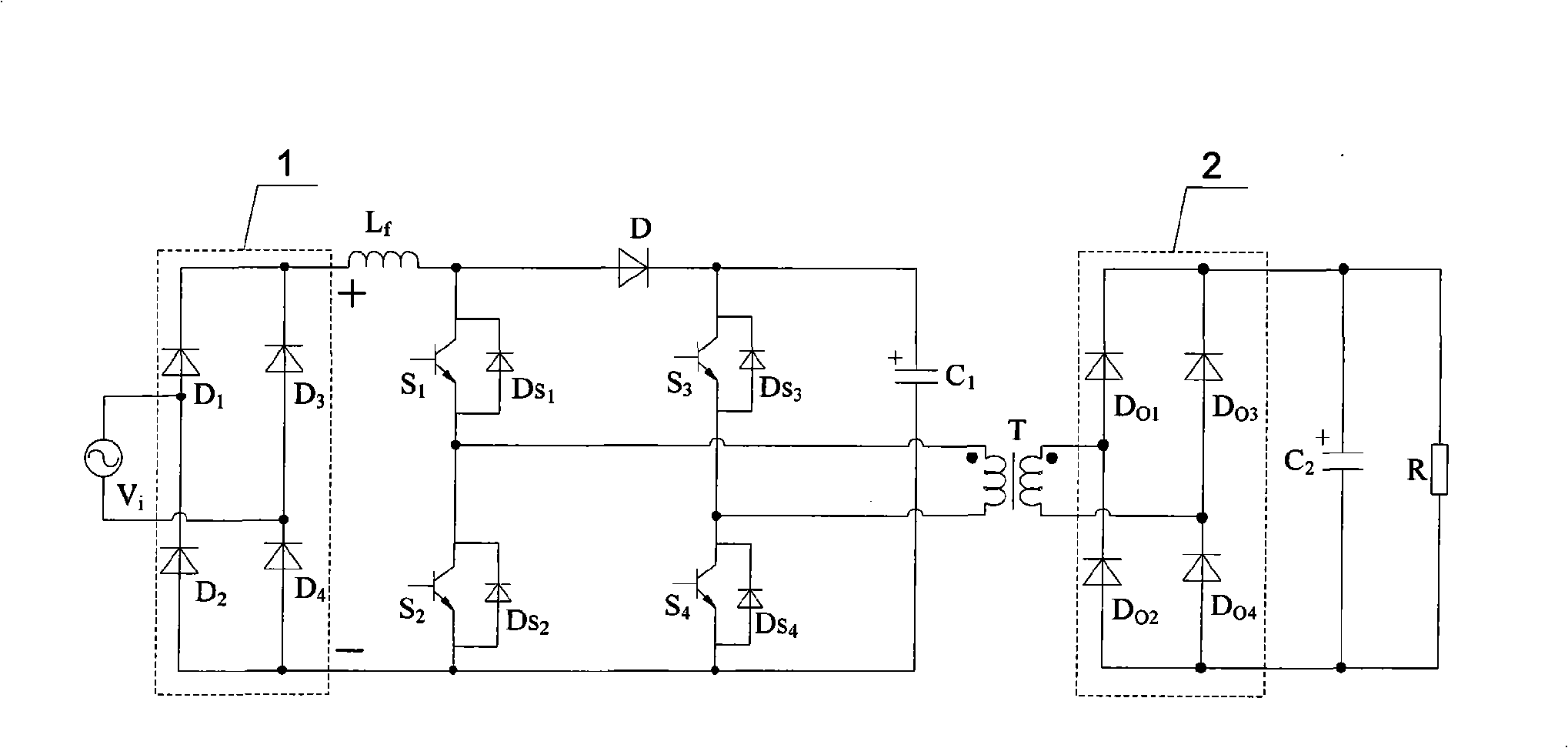
[0018] Specific implementation mode one: the following combination figure 1 and Figure 5 Describe this embodiment, the single-phase single-stage bridge power factor correction converter with passive clamping described in this embodiment includes a single-phase input rectifier circuit 1, a boost inductor L f , the first switch tube S 1 , the second switch tube S 2 , the third switch tube S 3 , the fourth switch tube S 4 , diode D, clamp capacitor C 1 , high-frequency transformer T, single-phase output rectifier circuit 2, output filter capacitor C 2 and load R,

[0019] The positive output terminal of the single-phase input rectifier circuit 1 and the boost inductor L f Connected to one end of the boost inductor L f The other end of the diode is connected to the anode of the diode D, and the cathode of the diode D is connected to the clamping capacitor C 1 Connected to one end of the clamp capacitor C 1 The other end of is connected with the negative output end of th...

specific Embodiment approach 2

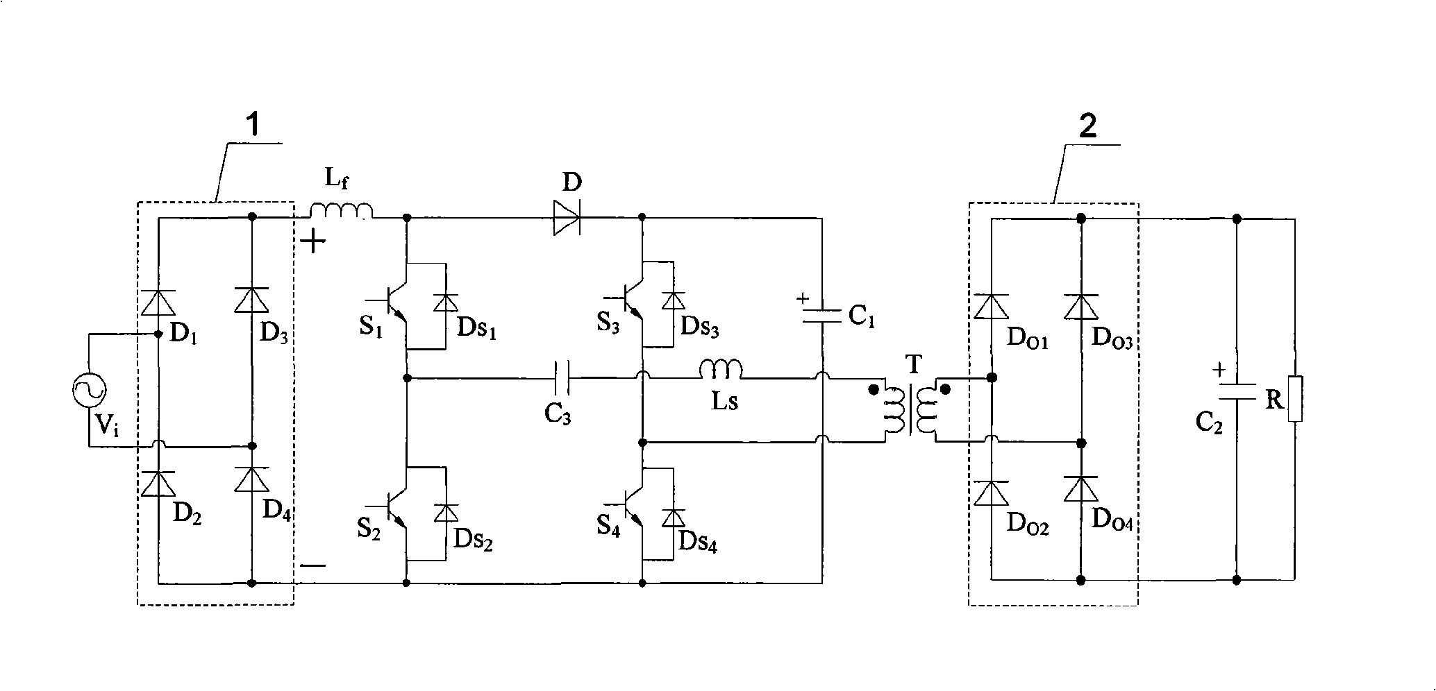
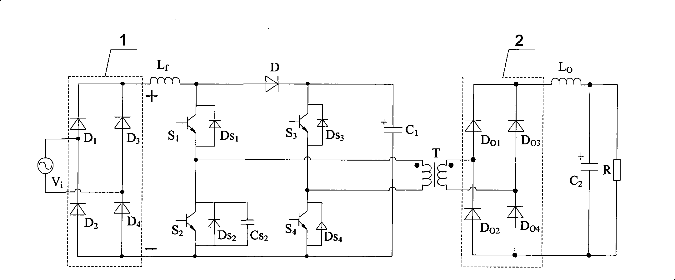
[0024] Specific Embodiment 2: The difference between this embodiment and Embodiment 1 is that the first switching tube S 1 , the second switch tube S 2 , the third switch tube S 3 and the fourth switching tube S 4 An IGBT power tube with a body diode or a MOSFET switch tube with a body diode are used, and other components and connections are the same as those in the first embodiment.

[0025] The first switch tube S 1 , the second switch tube S 2 , the third switch tube S 3 and the fourth switching tube S 4 The built-in body diodes are D S1 、D S2 、D S3 and D S4 .

[0026] body diode (D S1 、D S2 、D S3 or D S4 ) are respectively connected in antiparallel to four switching tubes (the first switching tube S 1 , the second switch tube S 2 , the third switch tube S 3 or the fourth switch tube S 4 ), when the four switch tubes use IGBT power tubes, the anode of the body diode is connected to the emitter of the IGBT power tube, and the cathode of the body diode is conn...

specific Embodiment approach 3

[0027] Specific implementation mode three: the following combination Figure 1 to Figure 8 This embodiment is described. The difference between this embodiment and the first embodiment is that the single-phase input rectifier circuit 1 adopts a full-bridge rectifier circuit composed of four diodes, and other components and connections are the same as those of the first embodiment.

[0028] The single-phase input rectification circuit 1 is composed of four diodes, and the four diodes are D 1 、D 2 、D 3 and D 4 . Single-phase AC supply voltage V i (input current i i ) is rectified by a single-phase input rectifier circuit 1 to become direct current.


PUM


Abstract

A passive clamping single-phase single-grade bridge type power factor correcting convertor and control method thereof belongs to the technical field of power and electron. The invention aims at solving the problems of large power frequency ripples at the output side, and slow circuit response speed of the existing single-grade power factor correcting circuit as well as the problem of generating voltage peak caused by the leakage inductance of a transformer when the transformer is employed to carry out electronic isolation on the input and output. The single-phase input rectification circuit of the invention converts an inputted single-phase alternating current into a direct current; an output bus is connected with a boost inductor, four switch pipe composition bridge structures, a diode and a clamping capacitance; the outgoing lines of the two bridge arm central points of the four switch pipe composition bridge structures are connected with a high-frequency transformer; the lateral sides thereof are connected with a single-phase output rectification circuit; the output end of the single-phase output rectification circuit is connected with an output filter capacitance and a load in parallel; in a switch period, the straight arm conducting and the aligning arm conducting of the switch pipes control alternatively. The invention is used for correcting the power factors.

Description

technical field [0001] The invention relates to a power factor correction technology, which belongs to the field of power electronics. Background technique [0002] The wide application of nonlinear loads such as power electronic devices brings a large number of harmonics, and the suppression of harmonics generated by power electronic devices mainly uses power factor correction (PFC) technology. Active power factor correction technology can be divided into two-stage type and single-stage type according to its circuit structure. In the two-stage power factor correction structure, the first stage is a power factor correction circuit, whose main function is to improve the input power factor; the second stage is a DC / DC converter, whose main function is to adjust the output voltage to match the load. The main advantage of the two-stage PFC is that each stage can be analyzed, designed and controlled separately, and has good versatility. The disadvantage is that there are many co...

Claims


Application Information

Patent Timeline
Patent Type & Authority Applications(China)
IPC IPC(8): H02M7/155H02M1/42H02M1/14
CPCY02B70/123Y02B70/10
Inventor 贲洪奇王大庆鲁志本
Owner HARBIN INST OF TECH
Why Eureka
Try Eureka