Potential therapy apparatus and combined electric therapy apparatus

A technology of potential therapy and electrotherapy, which is applied in the direction of therapy and electrotherapy, and can solve problems such as weak therapeutic effect

Inactive Publication Date: 2009-08-26
COCOROCA
View PDF1 Cites 4 Cited by
  • Summary
  • Abstract
  • Description
  • Claims
  • Application Information

AI Technical Summary

Problems solved by technology

This is problematic because when a constant potential like this is applied, the body becomes acclimated to this potential and as a result the therapeutic effect becomes weaker

Method used


Image

  • Potential therapy apparatus and combined electric therapy apparatus
  • Potential therapy apparatus and combined electric therapy apparatus
  • Potential therapy apparatus and combined electric therapy apparatus

Examples


Embodiment Construction

[0076] Next, a combined electrotherapy device according to an embodiment of the present invention will be described with reference to the drawings.

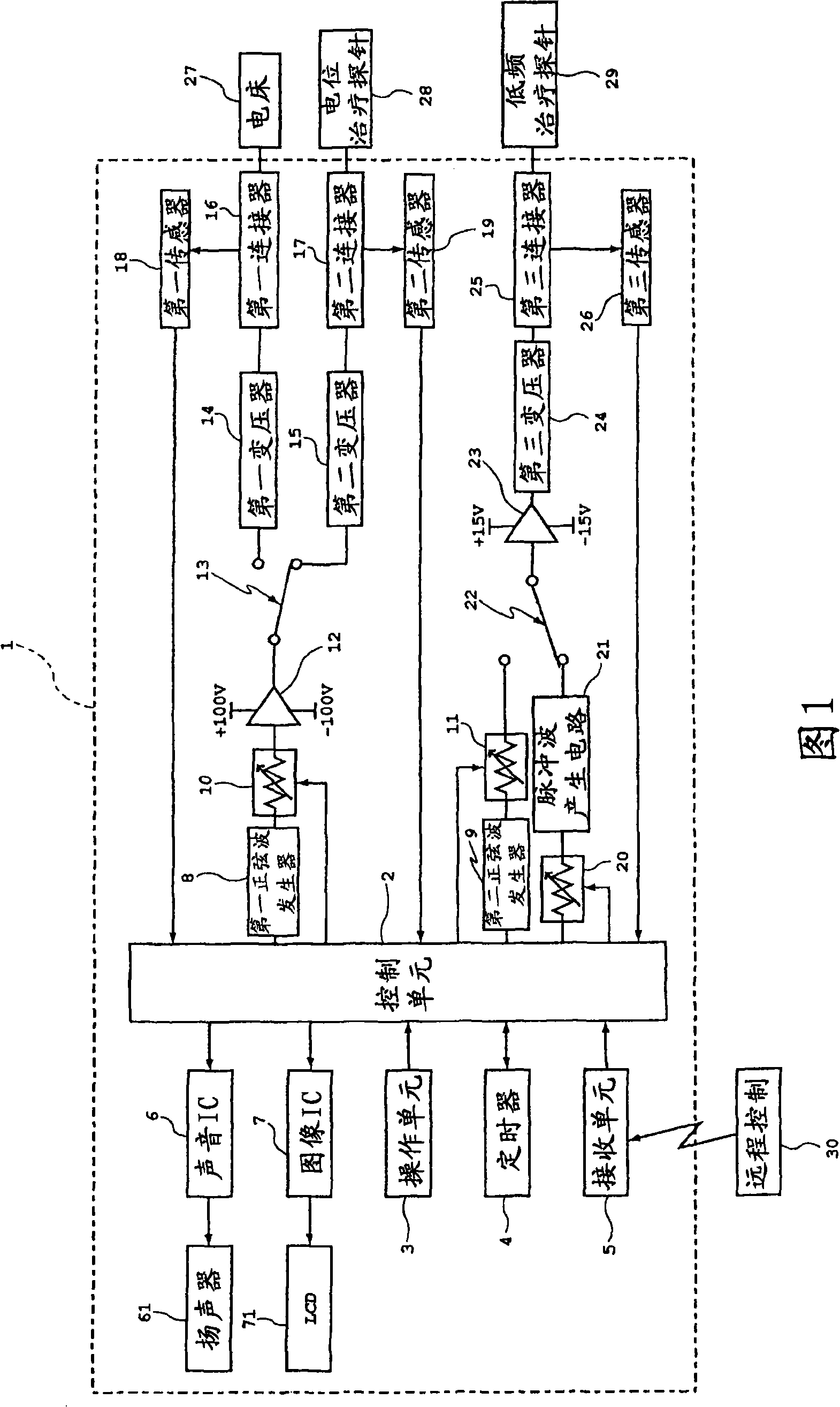
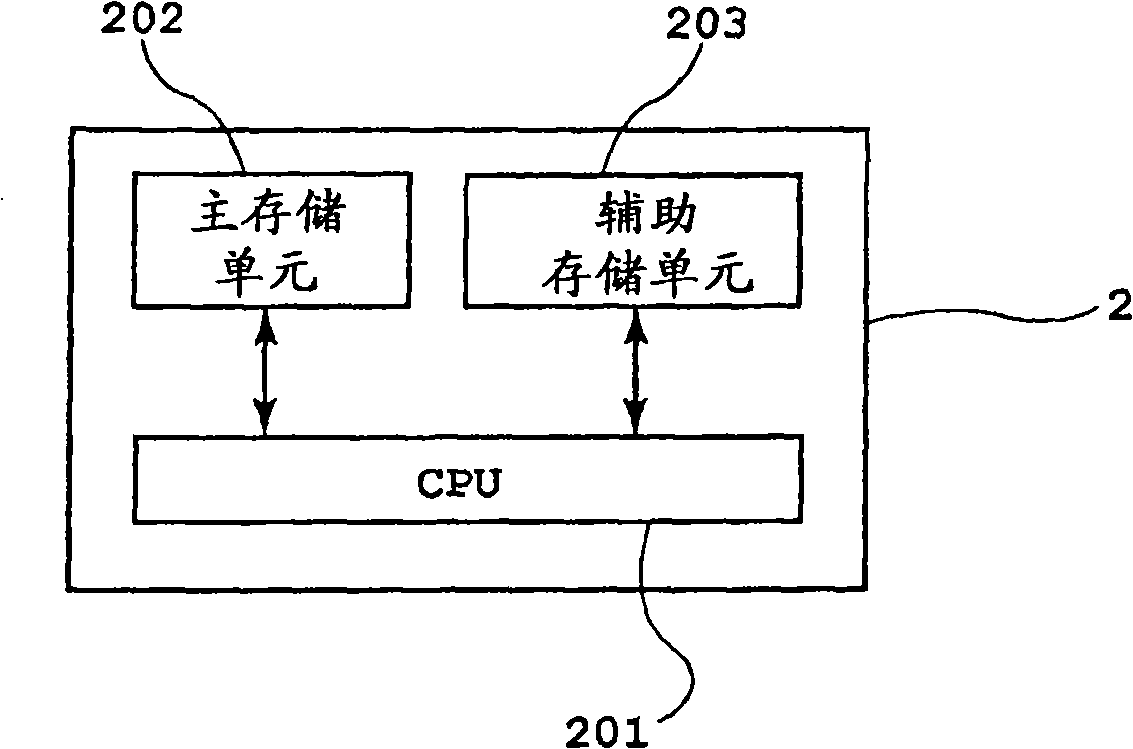
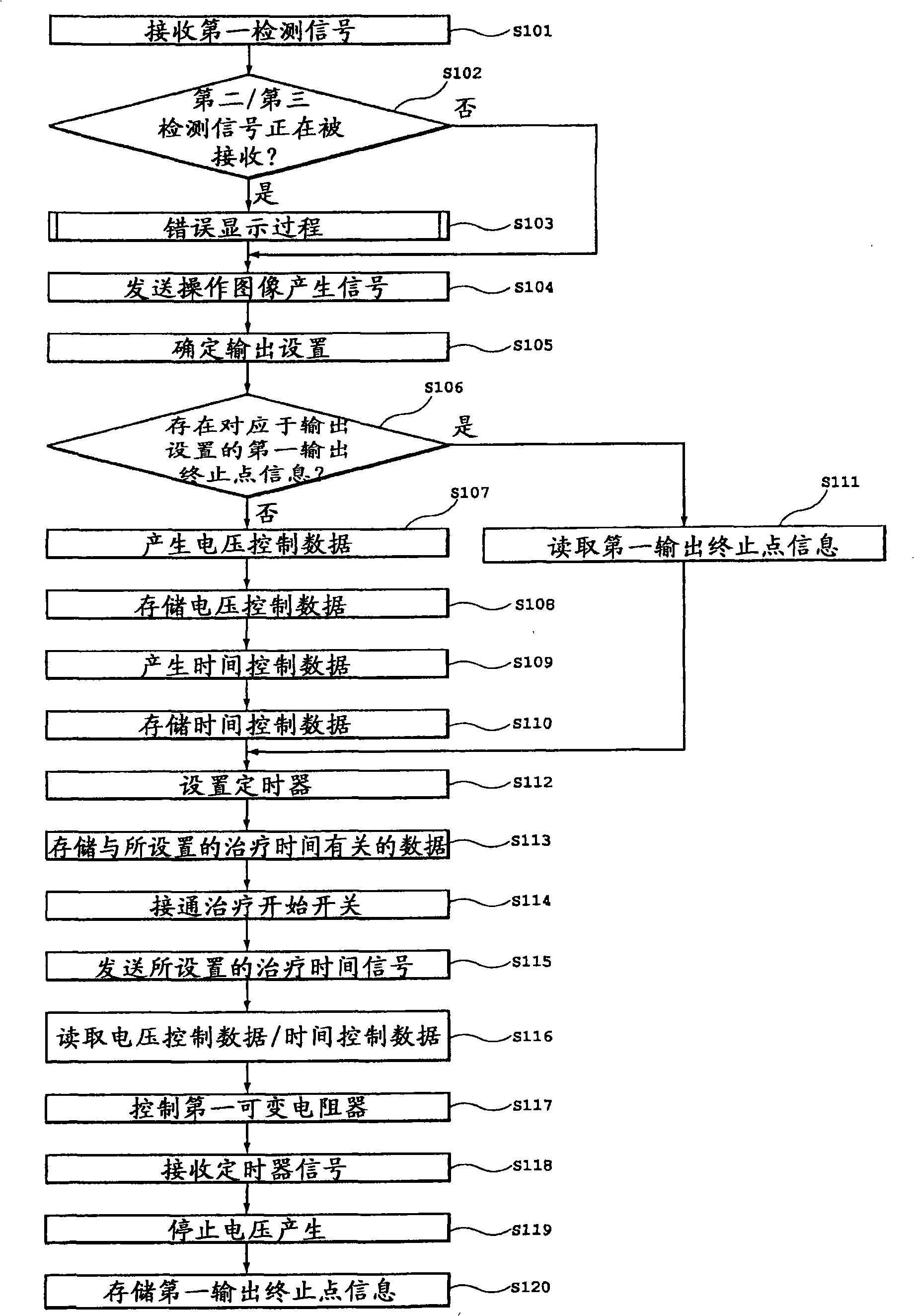
[0077] figure 1 is a circuit block diagram showing the combined electrotherapy device according to the present embodiment; figure 2 is a block diagram showing the control unit of the combined electrotherapy device according to the present embodiment; image 3 is a flow chart showing the process operation of electric potential therapy in the combined electrotherapy device according to the present embodiment; Figure 4 is a flow chart showing the process operation of the erroneous display in the combined electrotherapy device according to the present embodiment; and Figure 5 is a flowchart showing the process operation of low-frequency therapy in the combined electrotherapy device according to the present embodiment.

[0078] Such as figure 1 As shown, the combination electrotherapy device 1 according to the present embodimen...


PUM


Abstract

An electric therapy apparatus (1) of the invention comprises a voltage generating unit (14) for generating a predetermined voltage, a control unit (2) for varying the voltage generated by the voltage generating unit (14) and the output time of the voltage according to the 1 / f fluctuation cycle, potential therapy probes (27, 28) for applying the potential from the voltage generating section (14) to a therapy object. With this, it is prevented that the therapy object accustoms himself (herself) to the stimulation by the constant potential, it is possible to impart a relaxation feeling to the human body, and the therapy effect can be sustained.

Description

technical field [0001] The present invention relates to a potential therapy device that performs therapeutic treatment of a human body by applying an electric potential, and to a combined electrotherapy device that allows performing potential therapy and low-frequency therapy. Background technique [0002] Known therapeutic devices include potential therapy devices that treat headaches, stiff shoulders, chronic constipation, insomnia, etc., by applying AC high voltage potentials to a part or the whole of the human body, and treatment devices that treat headaches, stiff shoulders, chronic constipation, insomnia, etc. Low-frequency treatment device for stiff shoulders, muscle fatigue, etc. [0003] For example, in e.g. Figure 6 In the potential therapy device 100 shown in , the voltage supplied from the AC 100V power supply 101 to the transformer 102 through the switch SW and converted to a high voltage by the transformer 102 is controlled by three resistors R 1 , R 2 , R ...

Claims


Application Information

Patent Timeline
Patent Type & Authority Applications(China)
IPC IPC(8): A61N1/10A61N1/32
CPCA61N1/36021A61N1/32A61N1/36014A61N1/36071A61N1/321A61N1/322A61N1/36017A61N1/36034
Inventor 长谷三树彦苅田昌和
Owner COCOROCA
Why Eureka
Try Eureka