Gear shift device

A shifting device and technology of shifting gears, applied in the field of shifting devices, can solve problems such as easy increase in actuator capacity, easy generation of impact sound, and easy time-consuming, etc., so as to shorten the shifting action time, realize high-speed, suppress Effect of Actuator Capacity

Inactive Publication Date: 2009-08-26
HONDA MOTOR CO LTD
View PDF3 Cites 14 Cited by
  • Summary
  • Abstract
  • Description
  • Claims
  • Application Information

AI Technical Summary

Problems solved by technology

[0007] However, in the above-mentioned prior art, the rotation of the shift drum is carried out through the shift shaft parallel to it and through the ratchet mechanism. The gear shaft rotates forward and backward, so it is easy to take time to change gears
In addition, due to

Method used


Image

  • Gear shift device
  • Gear shift device
  • Gear shift device

Examples


Embodiment Construction

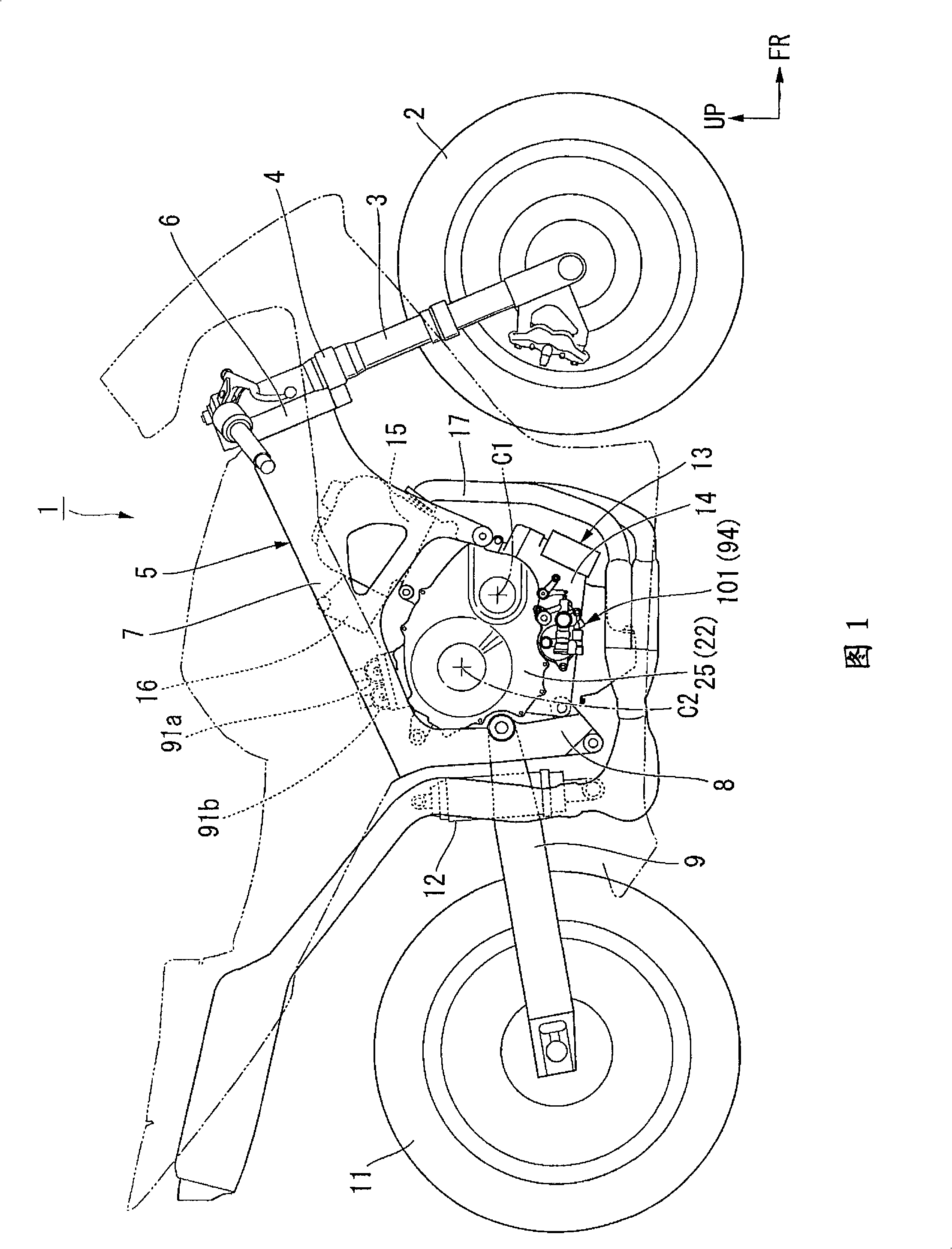
[0060]Hereinafter, one embodiment of the present invention will be described with reference to the drawings. In addition, directions such as front, rear, left, and right in the following description are consistent with directions in the vehicle unless otherwise specified. In addition, in the drawings, arrow FR indicates the front of the vehicle, arrow LH indicates the left side of the vehicle, and arrow UP indicates the upper side of the vehicle.

[0061] Such as figure 1 As shown, an upper portion of a front fork 3 pivotally supporting a front wheel 2 of a motorcycle (saddle type vehicle) 1 is pivotally supported on a head pipe 6 at the front end of a body frame 5 via a steering shaft 4 so as to be steerable. The main frame 7 extends rearward from the head pipe 6 and is connected to a pivot plate 8 . On the pivot plate 8 , the front end portion of the swing arm 9 is pivotally supported so as to be able to swing up and down, and the rear wheel 11 is pivotally supported on th...


PUM


Abstract

A gear shift device is used in a transmission of an engine, and includes: a shift drum that changes a speed change stage of the transmission according to a rotational position about an axis; an actuator having a driving shaft substantially orthogonal to this shift drum; a worm shaped barrel cam that is arranged parallel to the driving shaft of this actuator and that has a cam groove on an outer circumference; and a wheel gear that is coaxially fixed on the shift drum and that has a plurality of pins on an outer circumference. At least a pair of each pin of the wheel gear and the cam groove of the barrel cam is engaged with each other, and the shift drum is rotated by the actuator via the barrel cam and the wheel gear, to thereby change the speed change stage of the transmission.

Description

technical field [0001] The present invention relates to a shifting device for a transmission of an engine of a vehicle or the like. [0002] This application is based on Japanese Patent Application No. 2006-270104, and uses the content thereof. Background technique [0003] In the past, among the above-mentioned shifting devices, there is a device that rotates the shift drum through an actuator arranged in parallel to the drive shaft relative to the shift drum, thereby changing the shift speed of the transmission. The rotational position changes the gear position of the transmission (for example, refer to Patent Document 1). [0004] In addition, it is also conceivable to adopt a worm gear mechanism for making the drive shaft of the actuator substantially perpendicular to the transmission drum (for example, refer to Patent Document 2). [0005] Patent Document 1: Japanese Patent Application Laid-Open No. 11-82734 [0006] Patent Document 2: Japanese Patent Application Lai...

Claims


Application Information

Patent Timeline
IPC IPC(8): F16H63/18F16H25/12F16H61/28
CPCF16H61/32F16H63/18F16H2061/2892F16H61/688Y10T74/19279Y10T74/20177
Inventor 友田明彦盐崎智夫志岐健一菅野嘉久
Owner HONDA MOTOR CO LTD
Why Eureka
Try Eureka