Optical fiber distribution type sensor and optical fiber distribution type detection method

A technology of optical fiber distribution and detection method, which is applied in the direction of optical instrument testing, conversion of sensor output, transmission of sensing components by optical device, etc., can solve problems such as decrease in measurement efficiency, prolongation of measurement time, and increase of measurement points, and achieve high-efficiency temperature distribution or deformation distribution, high-efficiency measurement, and the effect of improving measurement efficiency

Inactive Publication Date: 2009-08-26
SUMITOMO ELECTRIC IND LTD
View PDF0 Cites 9 Cited by
  • Summary
  • Abstract
  • Description
  • Claims
  • Application Information

AI Technical Summary

Problems solved by technology

However, in this case, there is a problem that the measurement time is prolonged due to the increase of measurement points, and the measurement efficiency is reduced.

Method used


Image

  • Optical fiber distribution type sensor and optical fiber distribution type detection method
  • Optical fiber distribution type sensor and optical fiber distribution type detection method
  • Optical fiber distribution type sensor and optical fiber distribution type detection method

Examples


Embodiment Construction

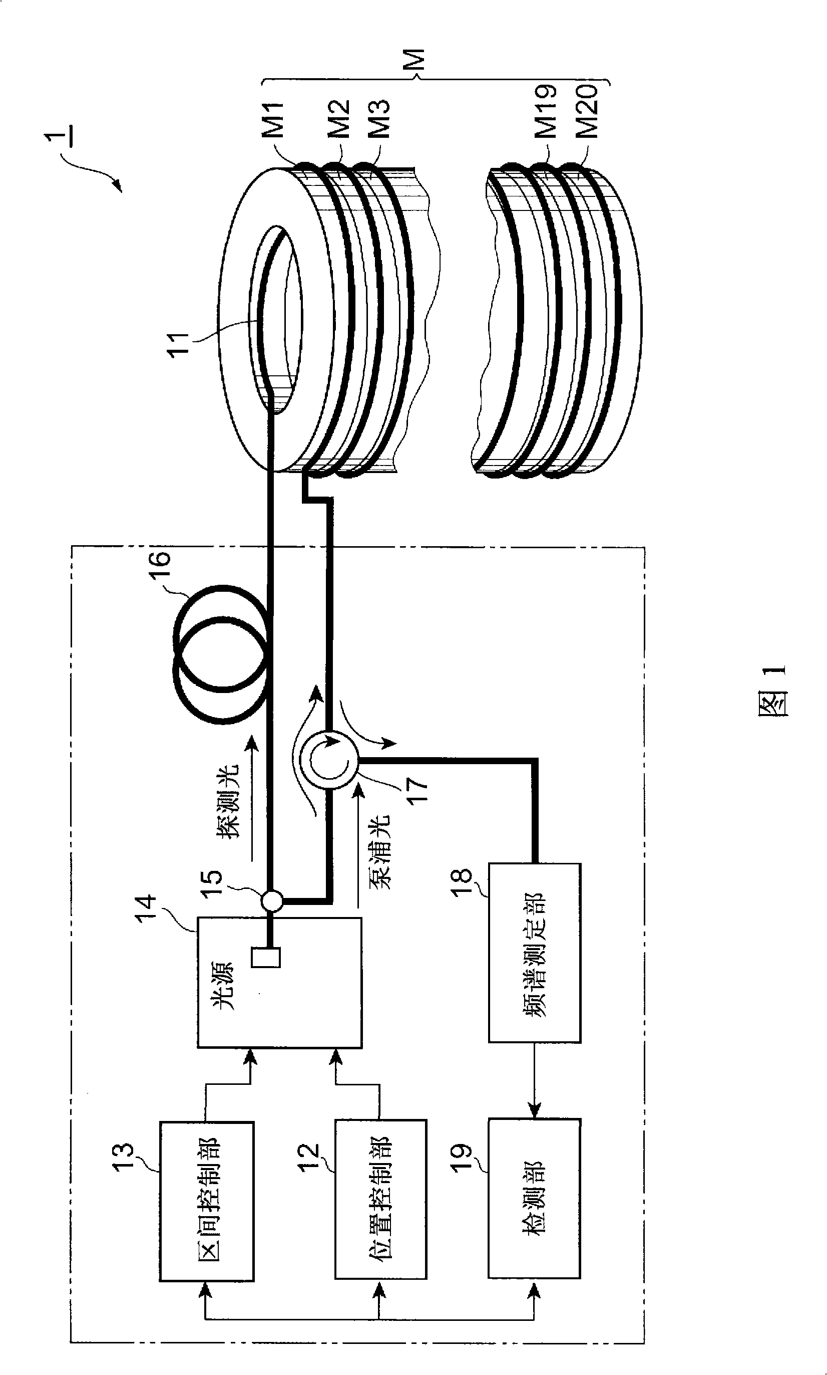
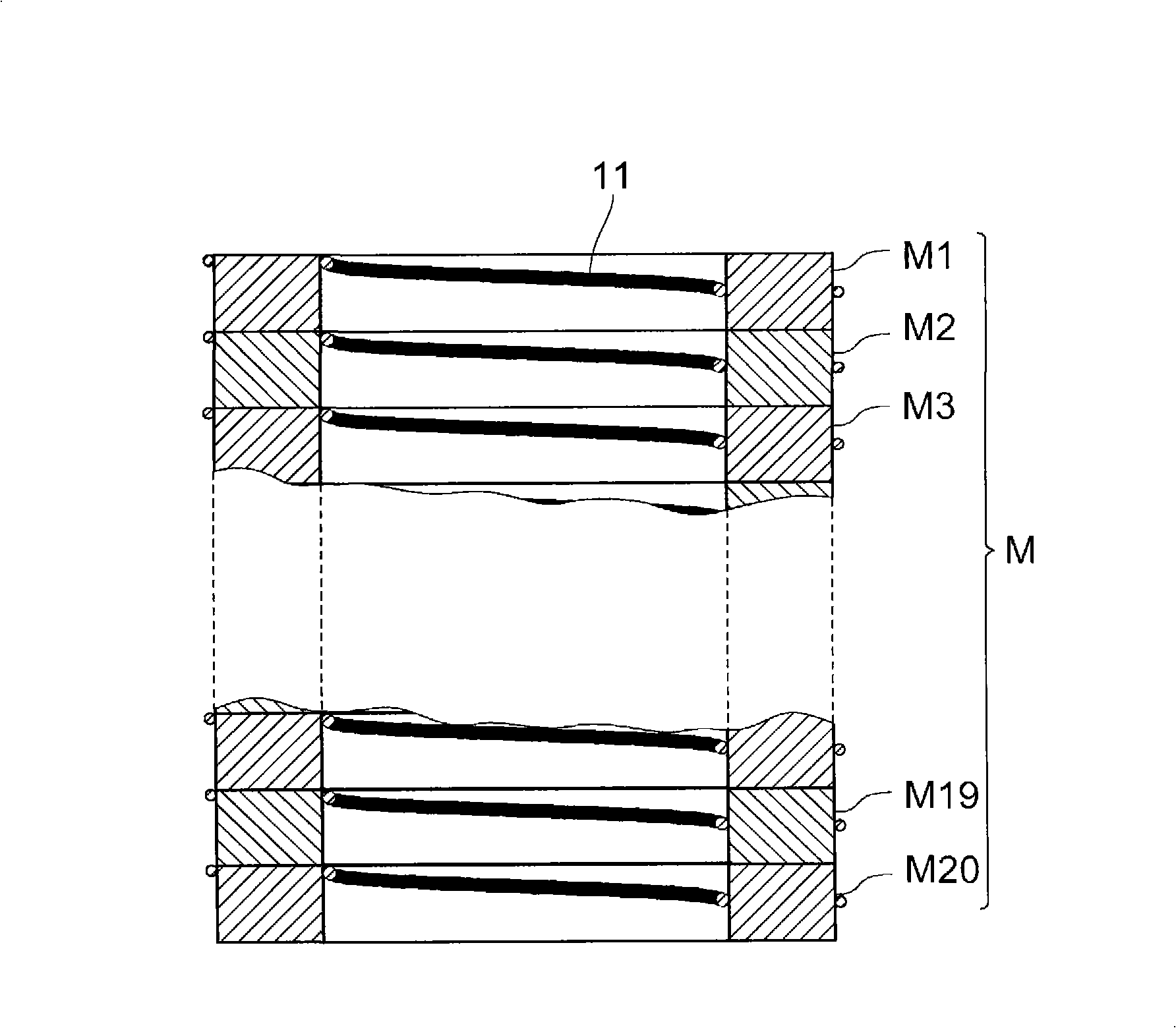
[0038] Below, refer to Figure 1 to Figure 7 Embodiments of the optical fiber distributed sensor and the optical fiber distributed detection method related to the present invention will be described in detail. In addition, in the description of the drawings, the same reference numerals are attached to the same parts and elements, and overlapping descriptions are omitted.

[0039] figure 1 It is a figure which shows the structure of one Example of the optical fiber distribution type sensor concerning this invention. The optical fiber distribution sensor 1 is a device that receives probe light output from an optical fiber 11 that has been gained by Brillouin scattered light, and based on data related to the BGS shape of the received probe light, The object M to be measured is subjected to temperature distribution measurement or strain distribution measurement, and the optical fiber 11 is installed in a state in which a part of the object M is in contact with the object M to be...


PUM


Abstract

The present invention relates to an optical fiber distribution type detecting method and the like equipped with a structure for enabling efficient measurement of a temperature distribution or strain distribution. This method regulates a modulation frequency and modulation index for probe light and pumping light opposingly incident on an object from a light source and a phase difference between the probe light and pumping light, thereby successively setting the length and location of search domains in a region to be measured. In particular, a detection process is executed while resetting the search domain length shorter at a predetermined interval of time or when an abnormality is detected. Thus partly changing the distance resolution for a specific region in the course of the detection process enables efficient measurement operations in a short time.

Description

technical field [0001] The invention relates to an optical fiber distributed sensor and an optical fiber distributed detection method for detecting the temperature change or deformation change of the optical fiber by using the Brillouin scattered light output from the optical fiber. Background technique [0002] The shape of the Brillouin gain spectrum (hereinafter referred to as BGS) of the Brillouin scattered light output from the optical fiber varies with the temperature and deformation of the optical fiber. Techniques for measuring temperature and deformation using such changes are known. [0003] As a technique for measuring BGS of Brillouin scattered light, for example, BOCDA (Brillouin Optical Correlation Domain Analysis) is known (see Non-Patent Document 1). In this BOCDA, probe light and pump light modulated with the same modulation frequency and modulation index are made to face each other from different ends of the optical fiber. At this time, BOCDA scans the di...

Claims


Application Information

Patent Timeline
IPC IPC(8): G01D5/353G01K11/12
CPCG01K11/32G01M11/085G01L1/242G01D5/353G01D5/35348
Inventor 屉冈英资山本义典
Owner SUMITOMO ELECTRIC IND LTD
Why Eureka
Try Eureka