
Double-motor skidproof differential drive axle of electric automobile

A dual-motor drive and electric vehicle technology, which is applied to vehicle components, control devices, transportation and packaging, etc., can solve the problems of vehicle impassability and waste of driving power of slipping wheel motors, etc., to facilitate the layout of the whole vehicle and improve the dynamic performance , The effect of improving the driving efficiency

Active Publication Date: 2009-09-02
BEIJING INSTITUTE OF TECHNOLOGYGY
View PDF0 Cites 68 Cited by
  • Summary
  • Abstract
  • Description
  • Claims
  • Application Information

AI Technical Summary

Problems solved by technology

At the same time, when driving, the vehicle is mainly driven by the motor of the wheel with a high adhesion coefficient relative to the road surface, which wastes the driving power of the motor on the side of the slipping wheel, and then if the vehicle is in a climbing state or encounters certain obstacles , the vehicle is likely to be impassable, which is not as good as a single-motor electric vehicle with a limited slip differential or a conventional vehicle

Method used


Image

  • Double-motor skidproof differential drive axle of electric automobile
  • Double-motor skidproof differential drive axle of electric automobile
  • Double-motor skidproof differential drive axle of electric automobile

Examples


Embodiment Construction

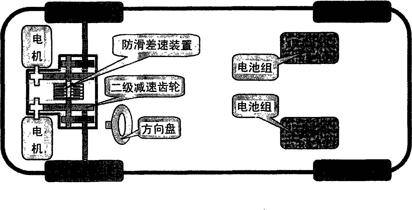
[0032] Such as figure 2As shown, the present invention is based on the following principles: a combined structure of double high-speed motors and two-stage reducers is adopted, and half-shaft transmission is adopted, and an anti-slip differential device is installed in the reduction gear box. When driving, the anti-skid differential device can be used to use the high adhesion of the ground on the other side to assist in controlling the slip, and play the role of the ASR (drive anti-skid) part. When the wheel speed difference is large, the non-slip differential device automatically realizes the flexible combination of the transmission gears on both sides, which improves the passing performance of the vehicle.

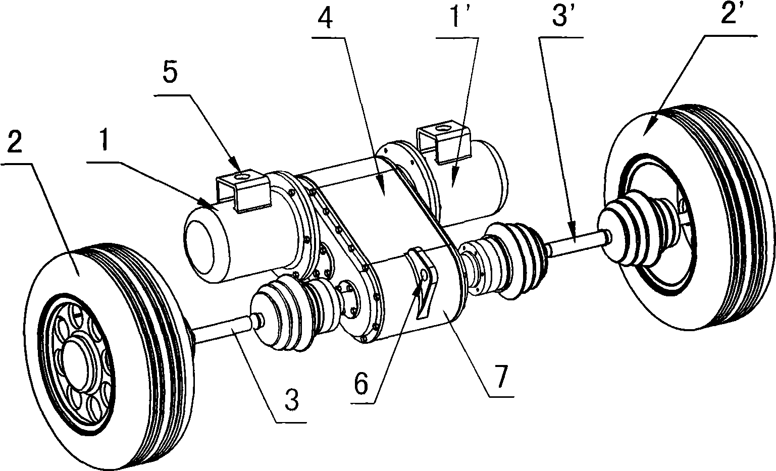
[0033] A specific embodiment of the dual-motor anti-slip differential drive axle according to the present invention will be described in detail below with reference to the accompanying drawings.

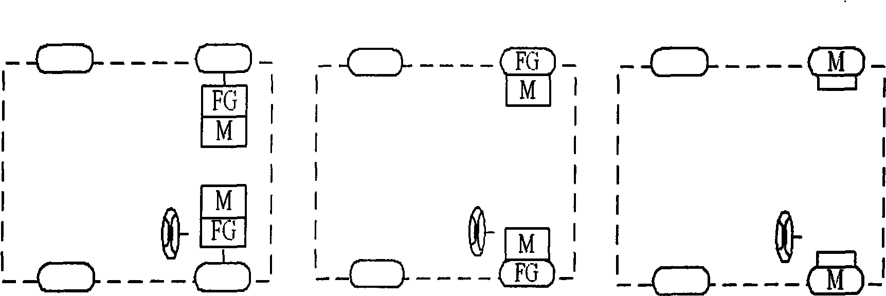
[0034] Figure 3-1 , 3-2 , 3-3, 3-4 are the appearance diagrams showin...


PUM


Abstract

The invention provides a double-motor skidproof differential drive axle used in electric automobiles, which comprises two driving motors, a speed reducer and an output axle which is connected with theThe invention provides a double-motor skidproof differential drive axle used in electric automobiles, which comprises two driving motors, a speed reducer and an output axle which is connected with the speed reducer. The two driving motors are arranged face to face in the middle of the driving axle and connected into a whole through the shell of the speed reducer. The power output by the two drivinspeed reducer. The two driving motors are arranged face to face in the middle of the driving axle and connected into a whole through the shell of the speed reducer. The power output by the two driving motors converges together and flows into the speed reducer; and then the power further drives the left and the right wheels of the electric automobile to rotate through the output axle which is conng motors converges together and flows into the speed reducer; and then the power further drives the left and the right wheels of the electric automobile to rotate through the output axle which is connected with the speed reducer. The driving motors and the speed reducer can be arranged in an engine chamber to achieve compact structure and save space. Simultaneously, in order to solve the problem oected with the speed reducer. The driving motors and the speed reducer can be arranged in an engine chamber to achieve compact structure and save space. Simultaneously, in order to solve the problem of skidding, a skidproof differential device is also arranged in the speed reducer.f skidding, a skidproof differential device is also arranged in the speed reducer.

Description

technical field [0001] The invention belongs to the field of electric vehicles, and more specifically relates to a dual-motor anti-slip differential drive axle suitable for driving electric vehicles. Background technique [0002] Due to the increasingly tense global energy sources, electric vehicles with high efficiency, energy saving and environmental protection have become the trend of future automobile development. Compared with electric vehicles driven by single motors, electric vehicles using dual-motor independent wheel drive (hereinafter referred to as dual-motor drive) schemes have many advantages, such as simplifying the mechanical transmission system, improving drive efficiency, and making full use of the on-board energy to increase the mileage; and the compact structure improves the space utilization of the car; the most critical thing is that the dual-motor drive scheme can achieve electronic differential speed by independently adjusting the speed of the two driv...

Claims


Application Information

Patent Timeline
IPC IPC(8): B60K17/12B60K17/16B60K17/28
Inventor 林程张治家马军张利鹏
Owner BEIJING INSTITUTE OF TECHNOLOGYGY
Learn More