Method and apparatus to control engine temperature for a hybrid powertrain

A technology of engine speed and engine, applied in the field of control system, can solve problems such as not being able to adapt to operating conditions, engine preheating, etc.

Active Publication Date: 2009-09-02
GM GLOBAL TECH OPERATIONS LLC
View PDF0 Cites 18 Cited by
  • Summary
  • Abstract
  • Description
  • Claims
  • Application Information

AI Technical Summary

Problems solved by technology

Such systems cannot adapt to changes in operating c

Method used


Image

  • Method and apparatus to control engine temperature for a hybrid powertrain
  • Method and apparatus to control engine temperature for a hybrid powertrain
  • Method and apparatus to control engine temperature for a hybrid powertrain

Examples


Embodiment Construction

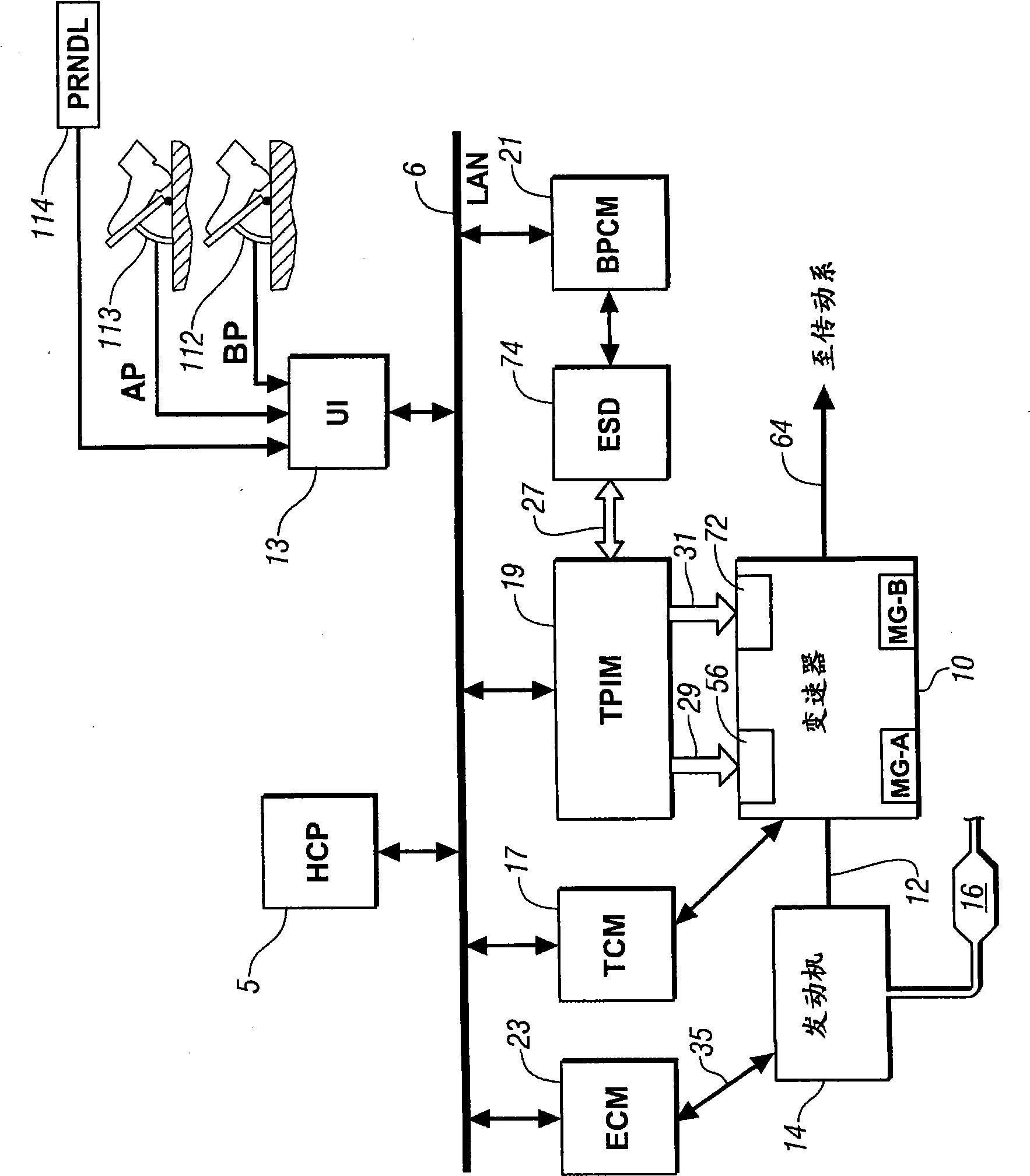
[0012] Referring now to the drawings, wherein the drawings are for illustration of certain exemplary embodiments only and not for limitation of these embodiments, figure 1 A schematic diagram of an exemplary powertrain and control system for executing a control program is depicted. The powertrain includes an internal combustion engine 14 , a first electric machine ('MG-A') 56 and a second electric machine ('MG-B') 72 . The internal combustion engine 14 , the first electric machine 56 and the second electric machine 72 each generate power that is transmitted through the transmission 10 to an output member 64 , such as for a vehicle's driveline (not shown). The power generated by the engine 14, the first electric machine 56, and the second electric machine 72 and delivered to the transmission 10 is characterized and described in terms of input torque and speed, referred to herein as Ti, T, respectively. A and T B , and the velocities are referred to as Ni, N A and N B .

...


PUM


Abstract

The present invention relates to a method and apparatus to control engine temperature for a hybrid powertrain. An internal combustion engine is connected to a transmission to transmit tractive power to a driveline. Engine coolant temperature is determined, and power output of the engine is adjusted based upon the coolant temperature and preferred coolant temperature range. The transmission is controlled to transmit tractive power to the driveline to meet an operator torque request based upon the adjusted power output of the engine.

Description

[0001] Cross References to Related Applications [0002] This application claims priority to US Provisional Application No. 60 / 985,983, filed November 7, 2007, which is hereby incorporated by reference into this application. technical field [0003] The present disclosure generally relates to control systems for hybrid powertrain systems. Background technique [0004] The statements in this section merely provide background information related to the present disclosure and may not constitute prior art. [0005] Powertrain control systems, including hybrid powertrain architectures, are used to meet operator demands for performance, such as torque and acceleration. Operator requirements for performance are balanced with other operator needs and regulations, such as fuel economy and emissions. Balancing operator performance requirements with other operator needs and regulations can be accomplished by quantifying engine power losses associated with particular operating condit...

Claims


Application Information

Patent Timeline
IPC IPC(8): B60W20/00B60W10/06B60W10/10F02D29/02
CPCY02T10/6286B60W2510/0685Y02T10/6226B60W2540/10B60W2540/12F02D2041/1433B60W10/06B60W2550/12B60W2510/1015B60W2510/244B60K6/547B60L2240/421B60K6/445B60L2240/445B60L2240/441B60W2710/0616Y02T10/6239B60W2510/0628F02D2250/18B60W50/087B60L2240/486B60K6/365F02D41/024B60W20/00B60W2510/0676B60W2710/1061B60K6/485B60K1/02B60W2510/068F02D41/1497Y02T10/26Y02T10/642F02D2200/021B60W2510/081B60W2510/0638B60W10/08B60W2555/20Y02T10/12Y02T10/62Y02T10/64B60W2050/0006B60W2510/06B60W20/10
Inventor A·H·希普J·L·莱蒂
Owner GM GLOBAL TECH OPERATIONS LLC
Why Eureka
Try Eureka