Reductant delivery apparatus with purging means

a technology of oxidative specie nox and purging means, which is applied in the direction of mechanical apparatus, engine components, machines/engines, etc., can solve the problems of difficult temperature control, damage to lines, and inability to effectively remove oxidative specie nox, etc., and achieve the effect of improving emission performan

Inactive Publication Date: 2013-03-07
YAN MI +1
View PDF6 Cites 43 Cited by
  • Summary
  • Abstract
  • Description
  • Claims
  • Application Information

AI Technical Summary

Benefits of technology

[0016]The present invention also provides a purging controller that triggers a purging event according to engine oil or coolant temperature, and controls the purging process. When engine oil or coolant temperature is lower than a threshold, a purging signal is generated. The purge control valve is then de-energized open, and the pump is run at a certain rate for a period of time while the injector is energized open. Using engine oil or coolant temperature to trigger purging avoids re-establishing pressure when key-off time is short, and thus helps improving emission performance for applications with frequent and short key cycles, such as that in a vehicle with frequent stops and goes.

Problems solved by technology

In lean combustion engines, due to the existence of large amount oxygen excess, passive means without extra dosing agents, such as that using a three-way catalyst, normally are not able to effectively remove the oxidative specie NOx as that in most of spark-ignition engines.
However, due to safety concerns and difficulties in handling pure ammonia, normally urea solution is used in ammonia SCR systems.
Also, since frozen reductant may damage the mechanical components in a dosing apparatus, such as the pump and the injector, and the temperature control normally is turned off after dosing finishes, in order to protect the dosing apparatus, reductant residue in the mechanical components needs to be purged before they are exposed to low temperature for a long time.
However, for reductant passage lines, due to distributed heating, it is difficult to control temperature in closed loop and locally over-heating could damage the lines.
However, during purging, since most of the reductant residue in the dosing apparatus needs to be drawn back to the reductant tank to avoid urea deposit and crystallization in the exhaust pipe, to which the dosing apparatus is fluidly connected, a reverse reductant flow needs to be created, and a complex flow control is then required.
This method involves multiple flow changes, and since partial flow change would create a fluid loop with the inlet fluidly connected to the outlet, resulting in purging failures, in addition to being able to swap the pump inlet with outlet, the system design and purge control should also avoid the fluid loop from happening.
Additionally, during purging, since the injector nozzle needs to be opened when the reductant residue in the injector is drawn back to the reductant tank, high temperature air in the exhaust pipe could come into the dosing apparatus, causing damage when it passes through the pump.
Without exhaust flow, it is difficult to obtain an accurate temperature at the injector nozzle due to temperature distribution in the exhaust pipe.
Furthermore, when air goes into the pump, the pumping efficiency drops significantly.
It is also difficult to clean the passage lines, especially the passage line connected to the injector, which normally is the longest passage line in the dosing apparatus.

Method used


Image

  • Reductant delivery apparatus with purging means
  • Reductant delivery apparatus with purging means
  • Reductant delivery apparatus with purging means

Examples


Embodiment Construction

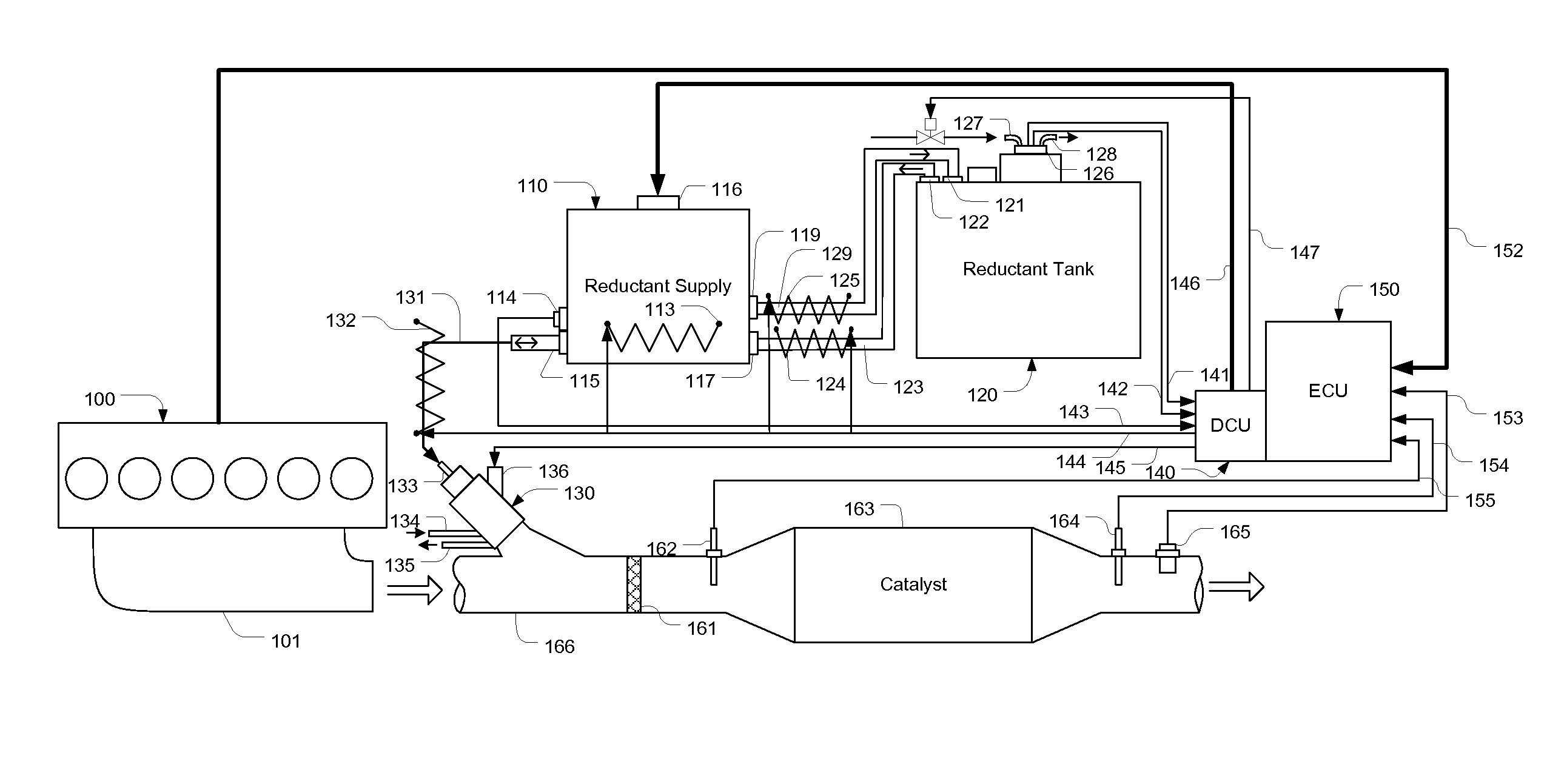
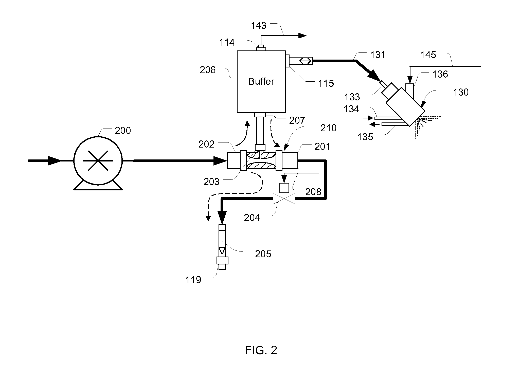
[0022]Referring to FIG. 1, in an engine exhaust gas treatment system, exhaust gas generated in an engine 100 enters a passage 166 through a manifold 101. On the passage 166, a reductant injector130 is installed. In an airless dosing system or an air-driven dosing system, in which reductant pressure is controlled in a common rail and reductant dosing amount is controlled by adjusting the open time of a nozzle fluidly coupled to the common rail, the solenoid valve of the injector 130 is controlled by a Dosing Control Unit (DCU) 140 through signal lines 145 electrically connected to a port 136, while in an air-assisted dosing system, in which reductant dosing rate is controlled with a metering pump, the injector has just a nozzle without active control means. Reductant to be injected by via the injector 130 is provided by a reductant supply module 110 through a reductant passage line 131 fluidly connected to a port 133. In a dosing system with active injector control, to avoid damages ...


PUM


Abstract

A dosing apparatus with purging means for delivering reductant into an exhaust gas treatment system of an internal combustion engine. The apparatus includes a first Venturi T connector with two high pressure ports and a low pressure port, and a purge control valve for switching from normal dosing to purging by controlling flow through the two high pressure ports. The apparatus may also include a second Venturi T connector and a reductant supply chamber for purging reductant residue in its pump and reductant passage lines. The apparatus may further include a purging controller that triggers a purging event according to engine oil or coolant temperature and controls the purging process after a dosing process completes.

Description

CROSS-REFERENCE TO RELATED APPLICATIONS[0001]Not ApplicableSTATEMENT REGARDING FEDERALLY SPONSORED RESEARCH OR DEVELOPMENT[0002]Not ApplicableREFERENCE TO SEQUENCE LISTING, A TABLE, OR A COMPUTER PROGRAM LISTING COMPACT DISC APPENDIX[0003]Not ApplicableFIELD OF THE INVENTION[0004]This present application claims priority from U.S. provisional application No. 61 / 573,295 having the same title as the present invention and filed on Sep. 2, 2011.[0005]The present invention relates to a dosing apparatus for delivering reducing agent (reductant) into an exhaust gas treatment system of an internal combustion engine.BACKGROUND OF THE INVENTION[0006]Environmentally harmful species in the exhaust gas emitted from an internal combustion engine, such as hydrocarbons (HC), carbon monoxide (CO), particulate matters (PM), and nitric oxides (NOx) are regulated species that need to be removed from the exhaust gas. In lean combustion engines, due to the existence of large amount oxygen excess, passive ...

Claims


Application Information

Patent Timeline
Patent Type & Authority Applications(United States)
IPC IPC(8): F01N3/20
CPCF01N3/208Y02T10/24F01N2610/1466Y02T10/12
Inventor YAN, MIQI, BAOHUA
Owner YAN MI
Why Eureka
Try Eureka