

Fuel supply apparatus for internal combustion engine
a fuel supply apparatus and internal combustion engine technology, which is applied in the direction of fuel injectors, machines/engines, electric control, etc., can solve the problems of restricted fuel supply temperature increase and achieve good combustion state, favorable exhaust emission, and suppress the variation of the fuel injection quantity of the in-cylinder injector
- Summary
- Abstract
- Description
- Claims
- Application Information
AI Technical Summary
Benefits of technology
Problems solved by technology
Method used
Image

Examples
first embodiment
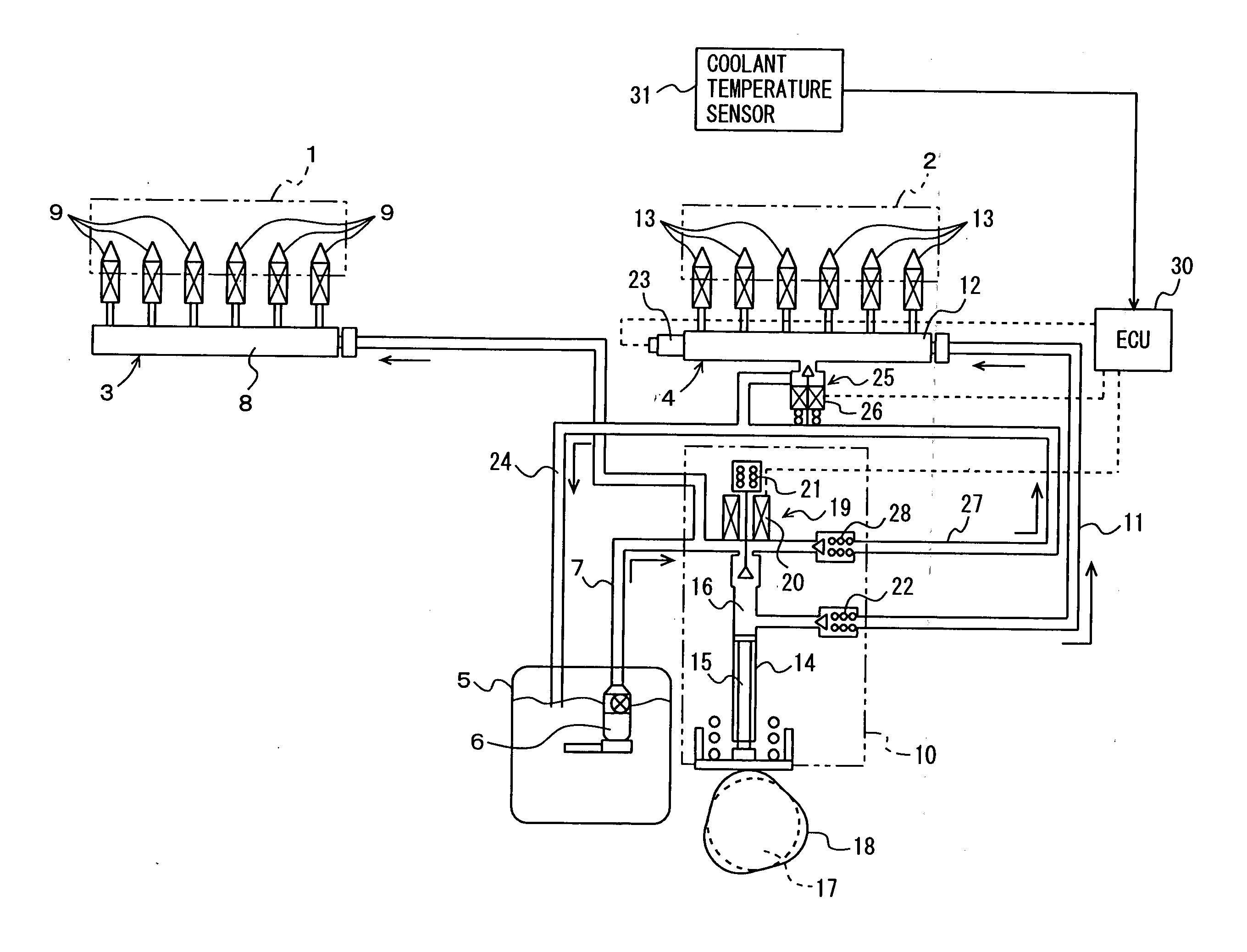
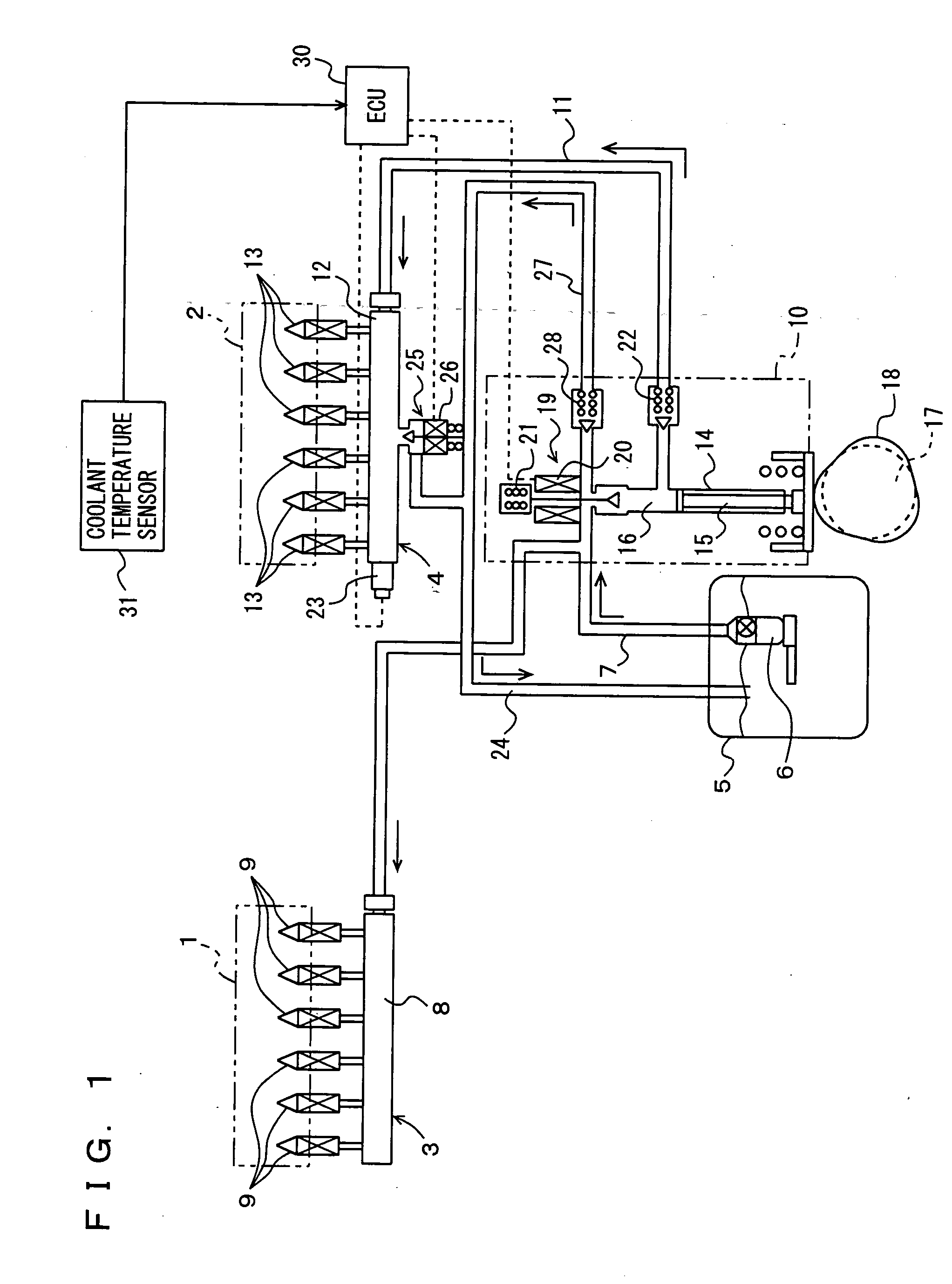
[0063] A fuel injection apparatus for an internal combustion engine according to the first embodiment of the present invention will now be described with reference to FIGS. 1 and 2. In the present embodiment, a fuel injection apparatus used for a 6-cylinder gasoline engine identified as the internal combustion engine will be described.
[0064] As shown in FIG. 1, the fuel injection apparatus includes a low-pressure fuel supply system 3 that injects fuel into an intake port 1 to provide an air-fuel mixture, which is supplied to a combustion chamber 2, and a high-pressure fuel supply system 4 that supplies fuel directly into combustion chamber 2. Low-pressure fuel supply system 3 and high-pressure fuel supply system 4 commonly use a low-pressure fuel path 7 through which fuel (referred to as the “low-pressure fuel”) is supplied from a fuel tank 5 to a low-pressure fuel pump 6.
[0065] Low-pressure fuel supply system 3 includes an intake port fuel delivery pipe 8 connected to low-pressur...
second embodiment
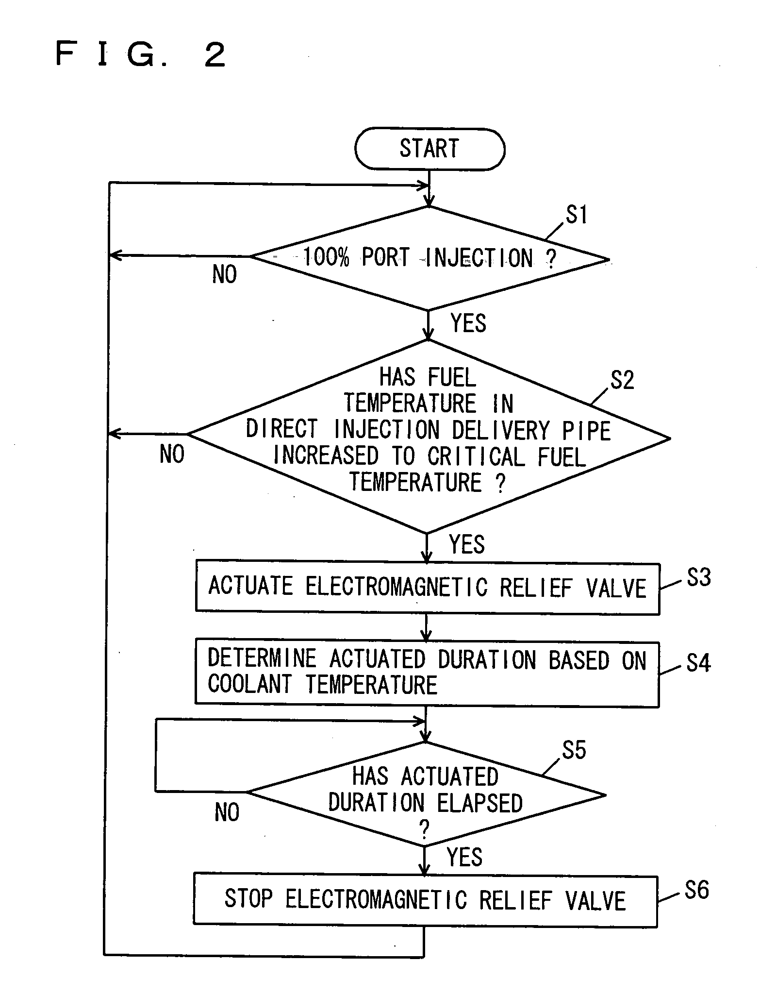
[0111] The second embodiment of the present invention will now be described with reference to FIGS. 3 and 4. The configuration of the fuel injection apparatus for the internal combustion engine according to the second embodiment is identical to the configuration shown in FIG. 1, and thus, detailed description thereof will not be repeated. The control procedure in the fuel injection apparatus is now described. FIG. 3 is a flowchart illustrating the control procedure in the second embodiment, and FIG. 4 is a timing chart illustrating the control states in the second embodiment.
[0112] The fuel injection apparatus of the second embodiment monitors the fuel pressure within in-cylinder injector 13, and, when the fuel pressure obtained by monitoring is not less than a reference pressure P1, it externally relieves the fuel within in-cylinder injection delivery pipe 12 to which in-cylinder injectors 13 are attached. The specific control procedure and control states for relieving the fuel wi...
third embodiment
[0129] The third embodiment of the present invention will now be described. FIG. 5 shows a fuel supply system 90 of an engine controlled by an engine ECU that is a control device according to the present embodiment. The engine is a V-type 8-cylinder gasoline engine, and has in-cylinder injectors 110 for injecting fuel into the respective cylinders, and intake manifold injectors 120 for injecting fuel into intake manifolds of the respective cylinders. It is noted that the present invention is not applied exclusively to such an engine, but is also applicable to a gasoline engine of another-type as well as a common rail diesel engine. Further, the number of high-pressure fuel pumps is not restricted to one, but may be two or more.
[0130] As shown in FIG. 5, this fuel supply system 90 includes a feed pump 100 provided in a fuel tank and for supplying fuel at a discharge pressure of low pressure (about 400 kPa corresponding to the pressure of a pressure regulator), a high-pressure fuel p...
PUM
 Abstract
Description
Claims
Application Information