Eureka AIR delivers breakthrough ideas for toughest innovation challenges, trusted by R&D personnel around the world.

Penetration soil layer original position elastic wave testing device

A test device and elastic wave technology, which is applied in the direction of measurement device, measurement of propagation speed, measurement of ultrasonic/sonic/infrasonic waves, etc. Improve the accuracy and speed, facilitate parallel testing and mutual comparison, and reduce the effect of testing costs

Inactive Publication Date: 2010-07-28
CIVIL AVIATION UNIV OF CHINA
View PDF4 Cites 0 Cited by
  • Summary
  • Abstract
  • Description
  • Claims
  • Application Information

AI Technical Summary

Problems solved by technology

[0003] However, the above two methods have the following problems: first, holes need to be drilled in the soil layer before the test, so the cost is high and the test speed is slow; in addition, the pressure of the air bag or water bag is needed to make the probe on the geophone contact with the hole wall. Contact, so the operation is time-consuming and laborious and the coupling effect is poor; in addition, due to the limitation of the resolution of the geophone, the test interval cannot be very small. For example, the vertical distance between the test points of the layer inspection method is at least 1m, so only a certain thickness range can be tested. The average wave velocity of the soil layer inside, so it only has the significance of statistical average, and it is impossible to achieve continuous and accurate testing

Method used


Image

  • Penetration soil layer original position elastic wave testing device
  • Penetration soil layer original position elastic wave testing device

Examples


Embodiment Construction

[0012] The penetrating soil layer in-situ elastic wave testing device provided by the present invention will be described in detail below with reference to the accompanying drawings and specific embodiments.

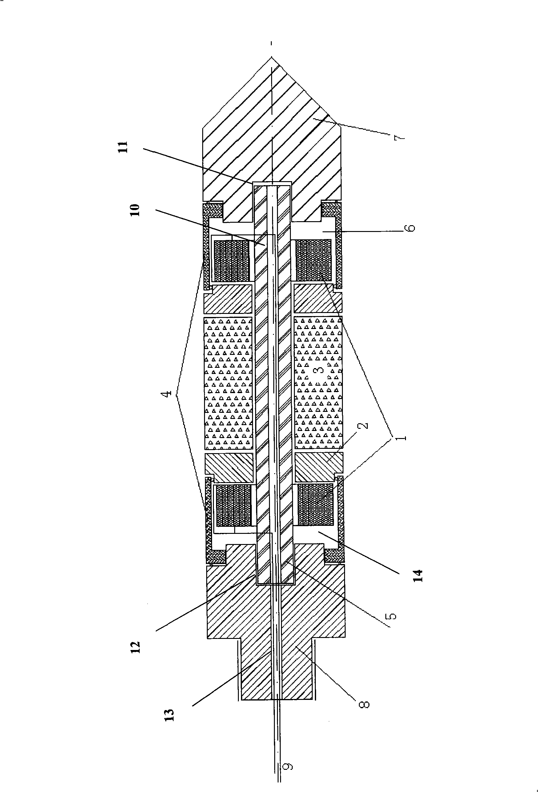
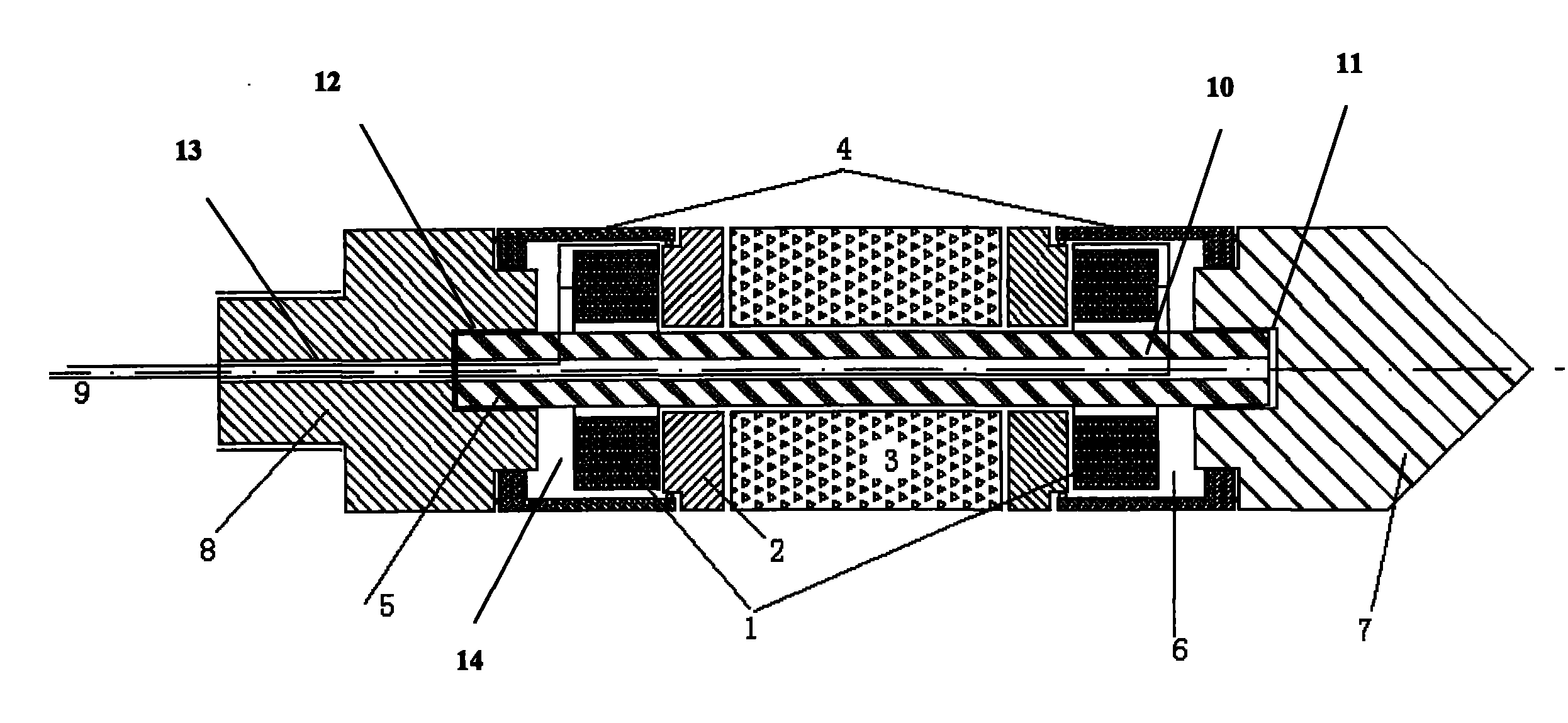
[0013] Such as figure 1 As shown, the penetrating soil in-situ elastic wave testing device provided by the present invention includes a connecting rod 5, an elastic wave damping block 3, two radiators 2, two casings 4, two piezoelectric ceramic ring vibrators 1, Conical penetrating head 7, probe connecting part 8 and two signal wires 9; the central part of the connecting rod 5 is formed with a central hole 10 for leading out the signal wire 9; the elastic wave damping block 3 is cylindrical, and the sleeve In the middle part of the outer circumference of the connecting rod 5; the two radiators 2 are ring-shaped, and respectively cling to the two ends of the elastic wave damping block 3 and sleeved on the outer circumference of the connecting rod 5; one end of the two she...


PUM


Abstract

The invention discloses a penetration soil layer original position elastic wave testing device which comprises a connecting link, an elastic wave damping block, two radiating bodies, two shells, two pThe invention discloses a penetration soil layer original position elastic wave testing device which comprises a connecting link, an elastic wave damping block, two radiating bodies, two shells, two ppth can be obtained. In addition, the device can simultaneously test the wave speed of transverse waves and longitudinal waves, and be combined with static sounding so as to be convenient for the parepth can be obtained. In addition, the device can simultaneously test the wave speed of transverse waves and longitudinal waves, and be combined with static sounding so as to be convenient for the parallel testing and the intercomparison of various soil indicators.allel testing and the intercomparison of various soil indicators.iezoelectric ceramic annular vibration generators, a tapered penetrating head, a probe connecting part and two signal wires. The penetration soil layer original position elastic wave testing device caiezoelectric ceramic annular vibration generators, a tapered penetrating head, a probe connecting part and two signal wires. The penetration soil layer original position elastic wave testing device can leave out the drilling step of the prior art so as to greatly reduce the testing cost. Meanwhile, the two piezoelectric ceramic annular vibration generators which are separated by a short distance an leave out the drilling step of the prior art so as to greatly reduce the testing cost. Meanwhile, the two piezoelectric ceramic annular vibration generators which are separated by a short distance are arranged in the device. A testing frequency which is at least two orders of magnitude higher than the original position shock excitation is adopted so as to greatly enhance the testing accuracy andre arranged in the device. A testing frequency which is at least two orders of magnitude higher than the original position shock excitation is adopted so as to greatly enhance the testing accuracy andthe testing speed of the soil layer elastic wave speed in the course of foundation perambulation, thereby the regular pattern of change of the continuous soil layer elastic wave speed following the d the testing speed of the soil layer elastic wave speed in the course of foundation perambulation, thereby the regular pattern of change of the continuous soil layer elastic wave speed following the de

Description

technical field [0001] The invention belongs to the technical field of geotechnical engineering exploration, in particular to a penetrating soil layer in-situ elastic wave testing device. Background technique [0002] The elastic wave velocity of the soil layer is widely used in site soil classification, foundation soil classification in seismic zoning, building anti-seismic foundation design and vibration analysis. Therefore, in engineering construction, the elastic wave velocity test of the site or foundation soil layer is a very important basic Work. At present, in-situ testing of soil elastic wave velocity mainly includes two methods: layer detection method and cross-hole method. Among them, the layer detection method needs to drill a hole in the soil layer first, then place the geophone at the depth of the soil layer to be tested, and then use the tapping method on the ground to excite vibration or in-hole vibration, so as to measure the soil layer above the geophone ...

Claims


Application Information

Patent Timeline
Patent Type & Authority Patents(China)
IPC IPC(8): G01H5/00
Inventor 程国勇
Owner CIVIL AVIATION UNIV OF CHINA
Why Eureka
Eureka Blog
Learn More