Lens driving device

A lens drive device and lens technology, applied in the field of photography, to achieve the effects of increased magnetic field utilization, enhanced magnetic field strength, and improved EMI

Inactive Publication Date: 2013-04-24
JOHNSON ELECTRIC SHENZHEN
View PDF4 Cites 0 Cited by
  • Summary
  • Abstract
  • Description
  • Claims
  • Application Information

AI Technical Summary

Problems solved by technology

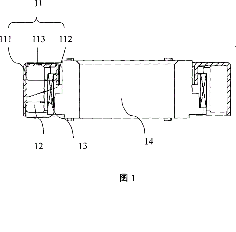
[0004]The magnetic flux direction of the magnet 12 is Fig. 1 shown in the direction of the arrow, because the lens holder 114 is a moving part, therefore, the inner ring 112 of the iron shell is shorter than the length of the outer ring 111 and the magnet 12, and the magnetic force that the magnet 12 sends More parts of the flux cannot enter the inner ring 112, and this part of the magnetic flux that fails to enter the inner ring encounters a large reluctance, so the magnetic field where the corresponding coil part is located is relatively weak, and the utilization rate of the magnetic field is low.

Method used


Image

  • Lens driving device
  • Lens driving device
  • Lens driving device

Examples


Embodiment approach

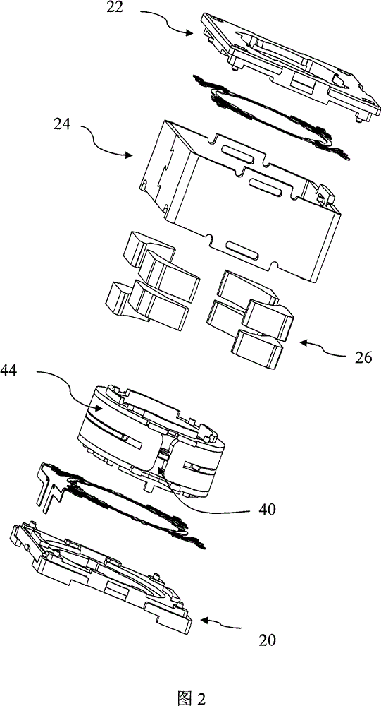
[0022] see Image 6 , as another embodiment of the present invention, the moving part may also include two semi-cylindrical coils, which are respectively fixed to both sides of the lens holder 40 by pasting or the like, and each semi-cylindrical coil corresponds to two sets of magnets.

[0023] see Figure 7 , as another embodiment of the present invention, the moving part may also include four arc-shaped coils, each coil corresponds to a group of magnets, and the currents flowing through the four coils have the same direction, that is, all of them are viewed from the same direction. Clockwise or all counterclockwise.

[0024] In the above embodiment, the lens driving device can be approximately square, cylindrical or other shapes, correspondingly, the iron shell 24 can be approximately square, circular or other shapes, and the lens holder 40 can be square, cylindrical or other shapes, The plurality of magnets 26 can be divided into several groups along the circumference of ...


PUM


Abstract

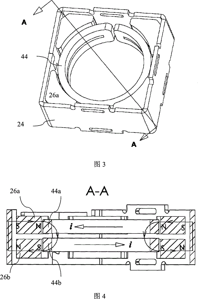
The invention provides a lens driving device, which comprises a fixed part, a moving part and a driving part used for driving the moving part to move relative to the fixed part; the fixed part comprises an iron case; the moving part comprises a lens bracket used for holding the lens; the driving part comprises a plurality of magnetic groups which are arranged along the circumferential direction ofthe lens; the magnetic groups are fixed on one of the iron case and the lens bracket; each magnetic group comprises at least two magnetic irons which are superposed along the axial direction of the lens; each magnetic iron is polarized along the radial direction of the lens; the polarities of two adjacent magnetic irons in one group are opposite; the driving part also comprises at least one coilwhich is fixed on one of the iron case and the lens bracket and faces to the magnetic groups; and the winding center of the coil is vertical to the axial direction of the lens. As adjacent magnetic irons in one group form a magnetic loop and pass through the coil, and each magnetic loop is short and has smaller magnetic resistance, the magnetic density where the coil is positioned is greatly strengthened, the magnetic leakage is reduced, the EMI is improved and the magnetic field utilization ratio is increased.

Description

technical field [0001] The invention belongs to the technical field of imaging, and in particular relates to a lens driving device. Background technique [0002] Video electronic products such as digital cameras, digital video cameras, mobile phones with camera functions, and notebook computers with cameras are usually equipped with lenses. A commonly used lens driving method in the prior art is to drive through a coil and a magnet to generate electromagnetic force. The lens moves on the optical axis. [0003] like figure 1 As shown, a lens driving device 1 in the prior art includes an iron shell 11, a magnet 12, a coil 13 and a lens frame 14, the magnet 12 is fixed to the iron shell 11 as a fixed part, and the coil 13 is fixed to the lens frame 14 As a moving part, the moving part can move relative to the fixed part. The iron shell 11 includes an outer ring 111, an inner ring 112 and a yoke 113, the outer ring 111 and the inner ring 112 are connected through the yoke 1...

Claims


Application Information

Patent Timeline
Patent Type & Authority Patents(China)
IPC IPC(8): G02B7/04H02K33/18
Inventor 李越张国际赵健
Owner JOHNSON ELECTRIC SHENZHEN
Why Eureka
Try Eureka