

Discharge coil for electromagnetic riveter and production method thereof
A technology of discharge coil and electromagnetic riveting gun is applied in the field of the manufacture of discharge coil and the field of discharge coil for electromagnetic riveting gun, which can solve the problems of reducing the outer size of the coil, the outer size of the coil is large, and the production procedure is complicated, and achieves the reduction of the outer size. , Improve the overall strength, improve the effect of heat dissipation conditions
Inactive Publication Date: 2010-12-01
NORTHWESTERN POLYTECHNICAL UNIV
View PDF1 Cites 4 Cited by
- Summary
- Abstract
- Description
- Claims
- Application Information
AI Technical Summary
Problems solved by technology
In order to overcome the disadvantages of large coil dimensions and complicated manufacturing procedures in the prior art, the present invention provides a discharge coil for an electromagnetic riveting gun, which uses countersunk nuts to reduce the coil dimensions
Method used
View moreImage
Smart ImageViewing Examples

Examples
Embodiment Construction
Login to View More PUM
 Abstract
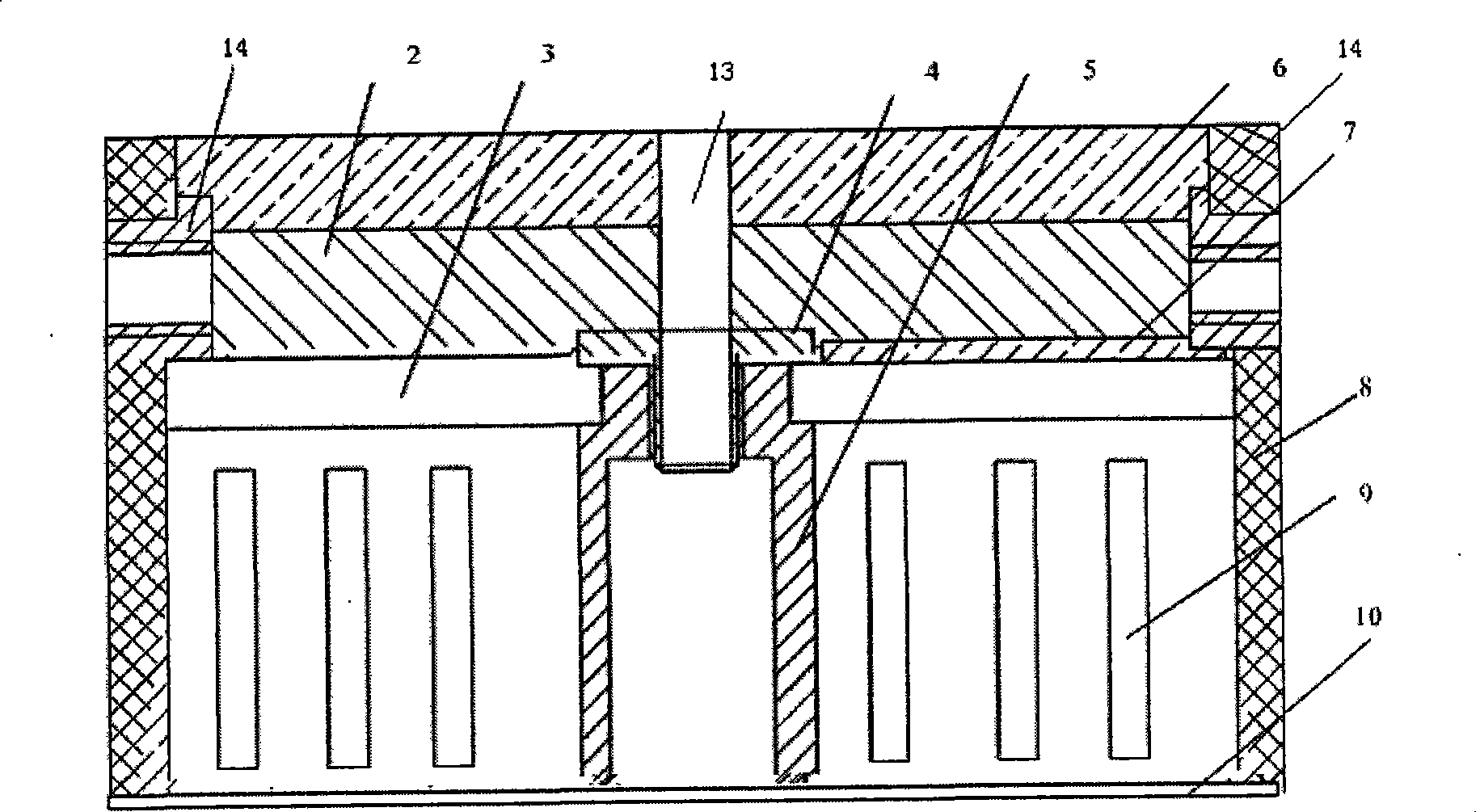
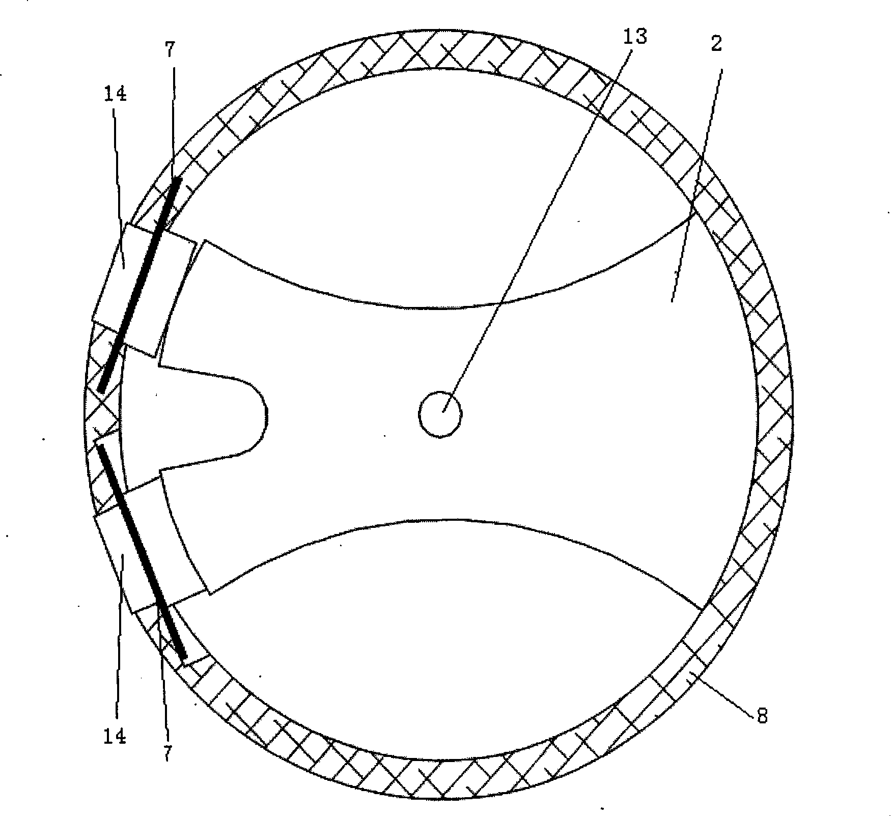
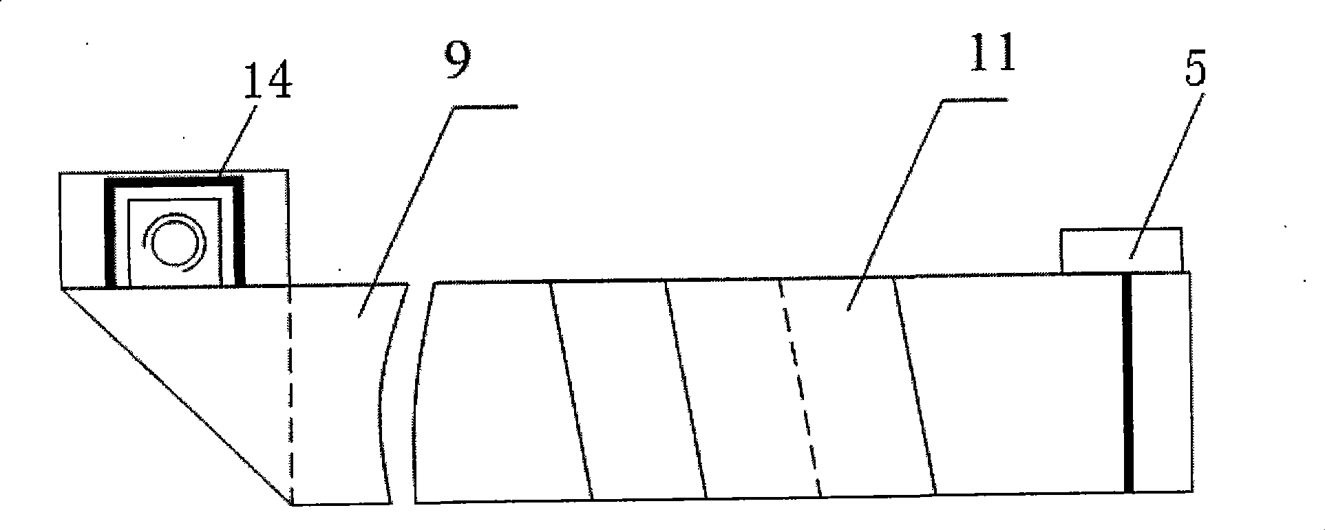
The invention discloses a discharge coil for an electromagnetic riveter, wherein the center of the coil is a core tube, an initial end of a copper strip is welded with the core tube, the core tube is The invention discloses a discharge coil for an electromagnetic riveter, wherein the center of the coil is a core tube, an initial end of a copper strip is welded with the core tube, the core tube issiating hole at the center of the coil improves heat dissipation conditions of the coil and reduces the temperature rise speed of the coil; the whole coil is packaged in the shell so as to ensure thatdiating hole at the center of the coil improves heat dissipation conditions of the coil and reduces the temperature rise speed of the coil; the whole coil is packaged in the shell so as to ensure thatthe coil can bear larger impact load; and the design of a partition improves the insulating property of the coil. the coil can bear larger impact load; and the design of a partition improves the insulating property of the coil.urrounded by layers of the copper strip wrapped by glass fabric, the continuous copper strip forms a cake-shaped disc in a shell, a round insulating board is arranged on the cake-shaped disc, the censurrounded by layers of the copper strip wrapped by glass fabric, the continuous copper strip forms a cake-shaped disc in a shell, a round insulating board is arranged on the cake-shaped disc, the center of the insulating board is a through hole matched with the upper end of the core tube, a supporting plate is arranged on the insulating board, an insulating layer is arranged on the supporting plater of the insulating board is a through hole matched with the upper end of the core tube, a supporting plate is arranged on the insulating board, an insulating layer is arranged on the supporting plate, a connecting line is fixedly connected with a countersunk nut on the shell, and the supporting plate is supported against two countersunk square nuts. The invention also discloses a method for prote, a connecting line is fixedly connected with a countersunk nut on the shell, and the supporting plate is supported against two countersunk square nuts. The invention also discloses a method for producing the discharge coil. The countersunk nuts are adopted, so the external dimension of the coil is reduced and the coil can be conveniently arranged into a small-scale electromagnetic riveter; a raducing the discharge coil. The countersunk nuts are adopted, so the external dimension of the coil is reduced and the coil can be conveniently arranged into a small-scale electromagnetic riveter; a rad
Description
Discharge coil for electromagnetic riveting gun and manufacturing method thereof technical field The invention relates to a discharge coil, in particular to a discharge coil for an electromagnetic riveting gun, and also to a manufacturing method of the discharge coil. Background technique Electromagnetic riveting technology has been widely used in the aerospace field. As the core component of electromagnetic riveting equipment, the discharge coil has an important impact on the performance of electromagnetic riveting equipment. Electromagnetic riveting equipment generally has two coils. The primary coil is generally a wound multi-turn pie-shaped coil, also known as a discharge coil. The secondary coil is generally an aluminum or copper plate with a certain thickness. The discharge coil is a key component of electromagnetic riveting equipment, and its working conditions are very harsh. When riveting, the discharge coil needs to bear the impact current of tens of thousands o...
Claims
Login to View More Application Information
Patent Timeline
 Patent Type & AuthorityPatents(China)
IPC IPC(8): H01F5/02H01F5/06B21J15/10
Inventor曹增强盛熙刘剑
OwnerNORTHWESTERN POLYTECHNICAL UNIV