
Drive train

A powertrain and torque technology, applied in the field of motor vehicles, can solve problems such as loss of comfort, failure overload, wrong interpretation of engine torque, etc., and achieve the effect of optimizing structural space

Inactive Publication Date: 2009-09-02
SCHAEFFLER TECH AG & CO KG
View PDF0 Cites 4 Cited by
  • Summary
  • Abstract
  • Description
  • Claims
  • Application Information

AI Technical Summary

Problems solved by technology

Such an affected rotational speed leads to a wrong interpretation of the derived engine torque when only one rotational speed sensor is used
This can lead, for example, to an overload torque on the driven elements, which can lead to overloading of these driven elements, loss of comfort and increased power and fuel consumption

Method used


Image

  • Drive train
  • Drive train
  • Drive train

Examples


Embodiment Construction

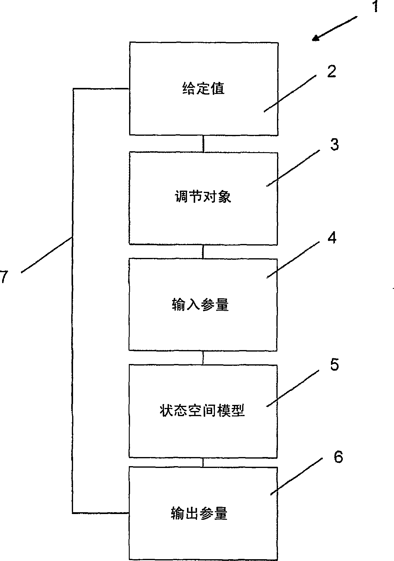
[0065] figure 1 An exemplary flow of regulation 1 according to the present invention is shown in . In box 2, a setpoint value for regulation 1 is provided, which can be calculated and output as an initial value by the engine control system. In the case of an internal combustion engine, the desired value can be a desired torque, which is predetermined by the driver using the accelerator pedal. Correspondingly, the desired torque can be adjusted as a function of other parameters such as engine characteristic factors, gears engaged in the transmission, vehicle operating conditions, road surface conditions and the like. In block 3 , setpoint 2 is used for the control object, which may include the internal combustion engine as well as downstream components such as clutches, dual-mass flywheels or powertrain components such as auxiliary units and downstream transmissions. In the case of a dual-mass flywheel, the setpoint output to the internal combustion engine is in particular co...


PUM


Abstract

The present invention relates to a drive train, in particular for a motor vehicle having a drive unit controlled by means of a control device and having a drive shaft and an element which is operatively connected to said drive shaft and is driven by it, wherein at least one state value of the driven element is read into the control device and the behaviour of the drive unit is influenced with the at least one state value.

Description

technical field [0001] The invention relates to a powertrain system and a method for operating the powertrain system, in particular for a motor vehicle, the powertrain system having a drive unit controlled by means of a control device, the drive unit having A drive shaft and an element operatively connected to and driven by the drive shaft. Background technique [0002] Arrangements in powertrain systems are already known in which an internal combustion engine is controlled by means of an engine management system. For example, the ignition timing, ie the ignition of the individual cylinders, is set via the injection timing and injection quantity. In order to characterize the engine state, the desired torque specified by the driver via the load lever is generally used here to determine the desired torque of the internal combustion engine from the engine speed detected by the sensor using the flywheel ring gear or the ignition mark by means of an engine characteristic map. ...

Claims


Application Information

Patent Timeline
IPC IPC(8): B60W50/06B60W10/04B60W30/20
CPCB60W2520/28B60W2050/0215B60W2510/0652B60W2050/021F02D2200/1006F02D2041/1415B60W30/20B60W2510/0661F02D41/1497F02D2200/1004B60W2510/0638B60W50/06F02D2041/1434B60W2510/0657B60W2050/0031
Inventor S·J·琼斯B·佩内克A·瓦尔特T·温克勒
Owner SCHAEFFLER TECH AG & CO KG
Learn More