Apparatus for manufacturing molten irons and method for manufacturing molten irons using the same

A technology of equipment, hot metal, applied in the direction of lighting and heating equipment, sustainable manufacturing/processing, furnace type, etc., can solve the problem of diffusion, etc.

Active Publication Date: 2011-03-30
浦项股份有限公司
View PDF0 Cites 0 Cited by
  • Summary
  • Abstract
  • Description
  • Claims
  • Application Information

AI Technical Summary

Problems solved by technology

The problem is that fine iron ore diffuses to the outside due to high-speed reducing gas
Therefore, there are still problems associated with the use of the above-mentioned packed bed reduction reactor and fluidized bed reduction reactor

Method used


Image

  • Apparatus for manufacturing molten irons and method for manufacturing molten irons using the same
  • Apparatus for manufacturing molten irons and method for manufacturing molten irons using the same
  • Apparatus for manufacturing molten irons and method for manufacturing molten irons using the same

Examples


Embodiment Construction

[0040] The following will refer to Figure 1-7 Exemplary embodiments of the present invention are explained. The exemplary embodiments are only intended to describe the present invention, and the present invention is not limited thereto.

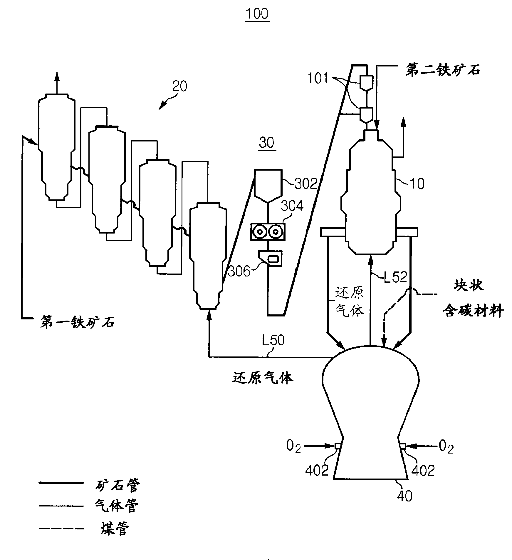
[0041] figure 1 An apparatus 100 for manufacturing molten iron according to a first exemplary embodiment of the present invention is schematically illustrated. figure 1 The apparatus 100 for manufacturing molten iron illustrated in FIG. 1 is only intended to describe the present invention, and the present invention is not limited thereto. Therefore, the structure of the user's equipment 100 for making molten iron can be modified into other forms.

[0042] exist figure 1 In , the ore pipe through which iron ore passes is marked as a thick solid line for convenience, and the gas pipe through which gas passes is marked as a thin solid line. In addition, the coal pipes through which the coal passes are marked with dashed lines.

[0043] ex...


PUM

PropertyMeasurementUnit
strengthaaaaaaaaaa
sizeaaaaaaaaaa
sizeaaaaaaaaaa

Abstract

The present invention relates to an apparatus for manufacturing molten irons and a method for manufacturing molten iron using the same. The method for manufacturing molten irons according to the preseThe present invention relates to an apparatus for manufacturing molten irons and a method for manufacturing molten iron using the same. The method for manufacturing molten irons according to the present invention includes reducing first iron ores by charging the first iron ores into a fluidized-bed reduction reactor; manufacturing compacted irons by compacting the reduced first iron ores; reducingnt invention includes reducing first iron ores by charging the first iron ores into a fluidized-bed reduction reactor; manufacturing compacted irons by compacting the reduced first iron ores; reducing second iron ores together with the compacted irons by charging the second iron ores and the compacted irons into a packed-bed reduction reactor, a size of the second iron ores is greater than a sizesecond iron ores together with the compacted irons by charging the second iron ores and the compacted irons into a packed-bed reduction reactor, a size of the second iron ores is greater than a sizeof the first iron ores; charging the reduced compacted irons and the second iron ores into a melter-gasifier connected to the packed-bed reduction reactor; preparing lumped carbonaceous materials as aof the first iron ores; charging the reduced compacted irons and the second iron ores into a melter-gasifier connected to the packed-bed reduction reactor; preparing lumped carbonaceous materials as aheating source for melting the reduced compacted irons and the second iron ores; charging the lumped carbonaceous materials into the melter- gasifier and then forming a coal packed-bed; and injecting heating source for melting the reduced compacted irons and the second iron ores; charging the lumped carbonaceous materials into the melter- gasifier and then forming a coal packed-bed; and injectingoxygen through a tuyere installed in the melter-gasifier and then manufacturing molten iron from the compacted irons and the second iron ores. oxygen through a tuyere installed in the melter-gasifier and then manufacturing molten iron from the compacted irons and the second iron ores.

Description

technical field [0001] The present invention relates to an apparatus for manufacturing molten iron and a method for manufacturing molten iron using the apparatus. More particularly, the present invention relates to an apparatus for manufacturing molten iron and a method for manufacturing molten iron using the apparatus to reduce fine iron ore having a wide range of particle sizes. Background technique [0002] The steel industry is a core industry that provides the basic materials needed in the construction industry as well as in the manufacture of automobiles, ships, household appliances and many other products we use. It is also one of the industries with the longest history accompanying human development. Iron foundries play an important role in the steel industry where steel is produced from molten iron after producing molten iron (which is pig iron in a molten state) by using iron ore and coal as raw materials and then supplied to consumption By. [0003] Currently, ...

Claims


Application Information

Patent Timeline
Patent Type & Authority Patents(China)
IPC IPC(8): C21B13/00
CPCC21B13/143C21B13/0013C21B13/0086F27B1/20C21B2100/04C21B13/002C21B2100/282C21B2100/64Y02P10/134C21B11/00C21B15/00
Inventor 许南释李后根金学童裴辰灿金倖久申明均
Owner 浦项股份有限公司
Why Eureka
Try Eureka