

Indoor unit for air conditioner
A technology for indoor units and air-conditioning devices, applied in air-conditioning systems, space heating and ventilation, space heating and ventilation details, etc., can solve problems such as cost and increase in water-absorbing materials, and achieve the purpose of suppressing dew condensation and water dripping and increasing ventilation resistance. Effect
- Summary
- Abstract
- Description
- Claims
- Application Information
AI Technical Summary
Problems solved by technology
Method used
Image

Examples
no. 1 approach
[0044] (1) Appearance of the air conditioner
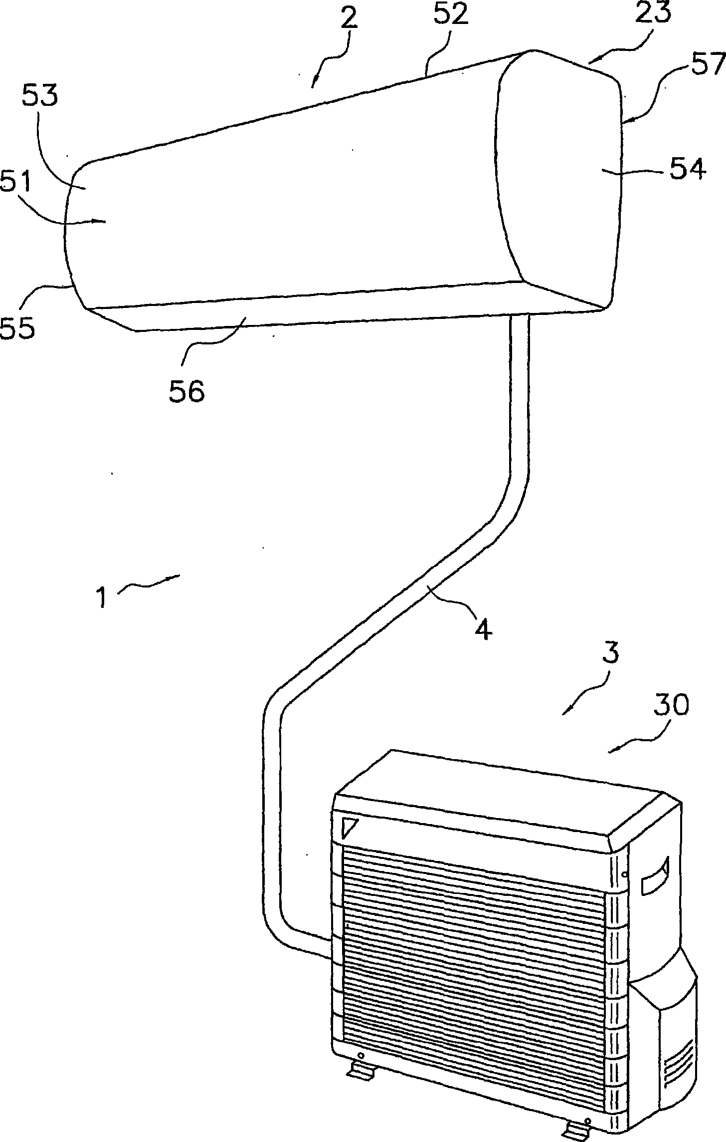
[0045] figure 1 It is a figure showing the appearance of the air conditioner 1 provided with the indoor unit 2 which concerns on 1st Embodiment of this invention.
[0046] This air conditioner 1 has: an indoor unit 2 installed on a wall or the like indoors; an outdoor unit 3 installed outdoors; and a refrigerant pipe 4 connecting the indoor unit 2 and the outdoor unit 3, and is housed in each unit The devices and valves in the housings 23 and 30 of 2 and 3 are connected to the refrigerant piping 4 to form a refrigerant circuit.
[0047] (2) Refrigerant circuit of air conditioner
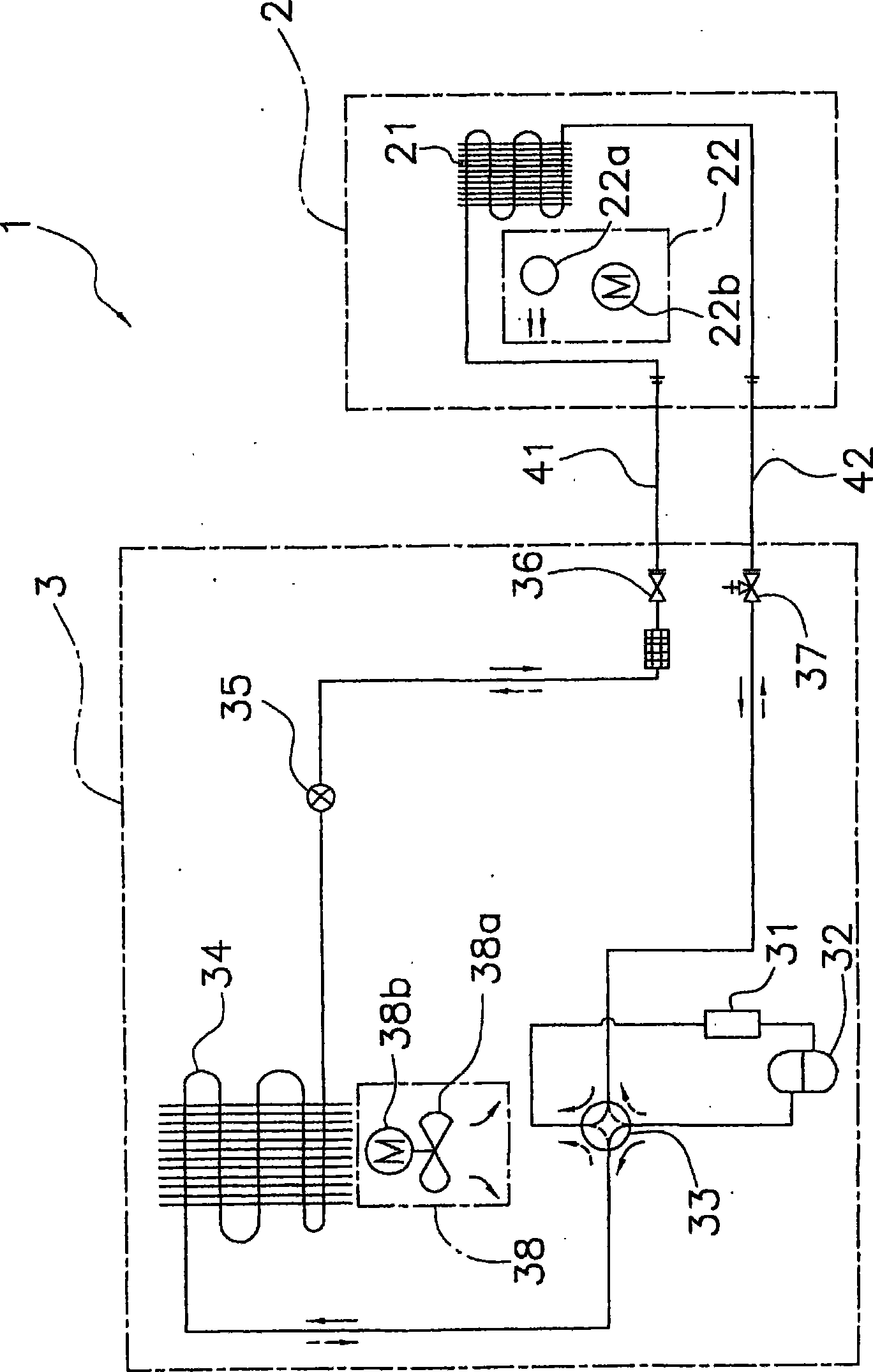
[0048] figure 2 It is a diagram showing a schematic refrigerant circuit of the air conditioner 1 . The refrigerant circuit is mainly composed of an indoor heat exchanger 21 , an accumulator 31 , a compressor 32 , a four-way switching valve 33 , an outdoor heat exchanger 34 and an expansion valve 35 .
[0049] The indoor unit 2 has an indoor heat ex...
PUM
 Abstract
Description
Claims
Application Information