Heat exchanger

A technology for heat exchangers and heat exchange tubes, applied in heat exchange equipment, indirect heat exchangers, heat exchanger types, etc., can solve the problems of inability to meet the overall performance, ventilation resistance and water resistance, and achieve improved effects and prevent The effect of increasing ventilation resistance and water resistance, and excellent heat dissipation performance

Inactive Publication Date: 2007-04-04
SHOWA DENKO KK
View PDF1 Cites 0 Cited by
  • Summary
  • Abstract
  • Description
  • Claims
  • Application Information

AI Technical Summary

Problems solved by technology

[0003] Recently, however, further improvement in the performance of radiator cores has been demanded. However, the radiator cores described in the above-mentioned gazettes have excellent heat dissipation performance, but have high air flow resistance and water flow resistance, and the overall performance cannot meet the requirements. The problem

Method used


Image

  • Heat exchanger
  • Heat exchanger
  • Heat exchanger

Examples


Embodiment Construction

[0017] Hereinafter, preferred specific examples of the present invention will be described with reference to the drawings. This specific example is an example in which the heat exchanger of the present invention is applied as a radiator core of an automobile air conditioner.

[0018] In addition, in the following description, the top and bottom and the left and right in FIG. 1 are referred to as up and down, and the left and right, the back side of the paper (upper side in FIG. 2) of FIG.

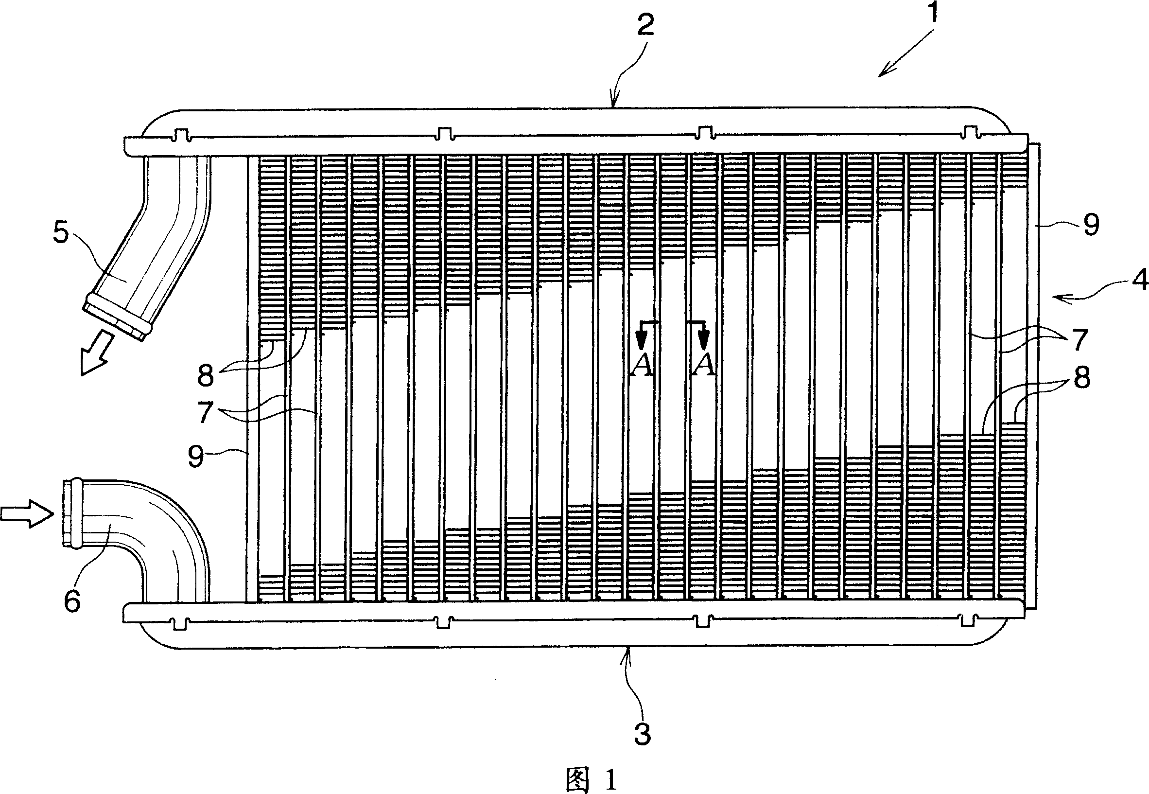
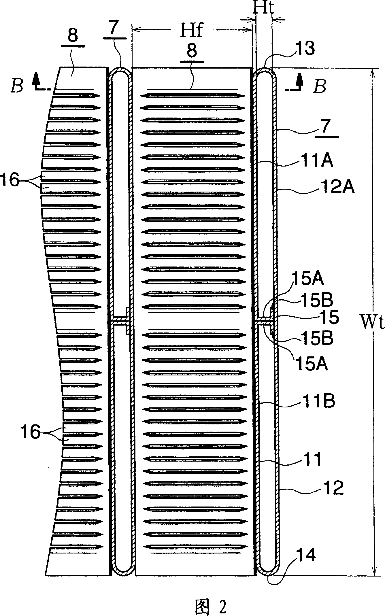
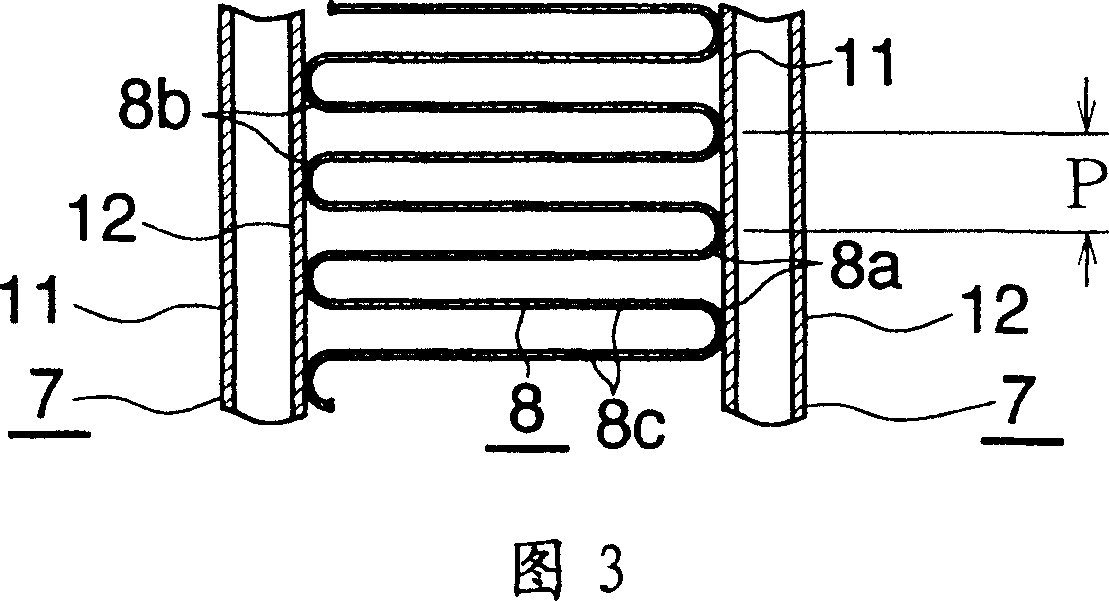
[0019] Fig. 1 shows the overall structure of a radiator core for automobile air conditioning to which the heat exchanger of the present invention is applied, and Figs. 2 and 2 and 3 show the structure of the main parts.

[0020] In Figure 1, the radiator core (1) is provided with: an upper water collection tank (2) and a lower water collection tank (3) made of aluminum, which are arranged at intervals in the vertical direction and are long in the left and right direction, and The heat exchange ...


PUM


Abstract

A heat exchanger to be used as a heater core includes a pair of header tanks spaced apart from each other, a plurality of flat heat exchange tubes which are disposed between the two header tanks at predetermined intervals along a longitudinal direction of the header tanks with their width direction coinciding with an air flow direction and whose opposite end portions are connected to the header tanks, and a plurality of corrugate fins each disposed between the adjacent heat exchange tubes. Each heat exchange tube has an inner height Ht of 0.7 mm to 1.2 mm and a width of 24 mm to 30 mm as measured in the air flow direction. Each corrugate fin has a fin height Hf of 5.5 mm to 8.5 mm. This heat exchanger exhibits excellent heat radiation performance and low resistance to air flow and water flow.

Description

Technical field [0001] The present invention relates to a heat exchanger suitable for use as a radiator core assembled in an automobile air conditioner of a vehicle, for example. The term "aluminum" mentioned in this specification and claims includes aluminum alloy in addition to pure aluminum. Background technique [0002] As a radiator core in an automobile air conditioner, the following radiator core is known heretofore. The radiator core is provided with a pair of water collection tanks arranged at intervals from each other; and the width direction faces the ventilation direction The method is arranged in the longitudinal direction of the water collection tank at intervals between the two water collection tanks, and the two ends of the flat heat exchange tubes connected to the two water collection tanks; and the wave top, wave bottom and connecting wave The top and bottom of the wave are formed by a flat connection part, and are arranged between adjacent heat exchange tubes. ...

Claims


Application Information

Patent Timeline
Patent Type & Authority Applications(China)
IPC IPC(8): F28D1/053
CPCF28D1/0391F28F1/126
Inventor 矢部隆须藤博之平山贵司
Owner SHOWA DENKO KK
Why Eureka
Try Eureka