Sewing machine

A technology for sewing machines and electric motors, applied to sewing machine components, sewing machine needle holders, sewing machine thread take-up devices, etc.

Active Publication Date: 2009-09-09
JUKI CORP
View PDF6 Cites 7 Cited by
  • Summary
  • Abstract
  • Description
  • Claims
  • Application Information

AI Technical Summary

Problems solved by technology

[0004] In addition, in existing sewing machines, such as Figure 19 As shown, in order to achieve no oil supply (grease oil supply) to the connecting portion 120 between the n

Method used


Image

  • Sewing machine
  • Sewing machine
  • Sewing machine

Examples


Embodiment approach 1

[0086]

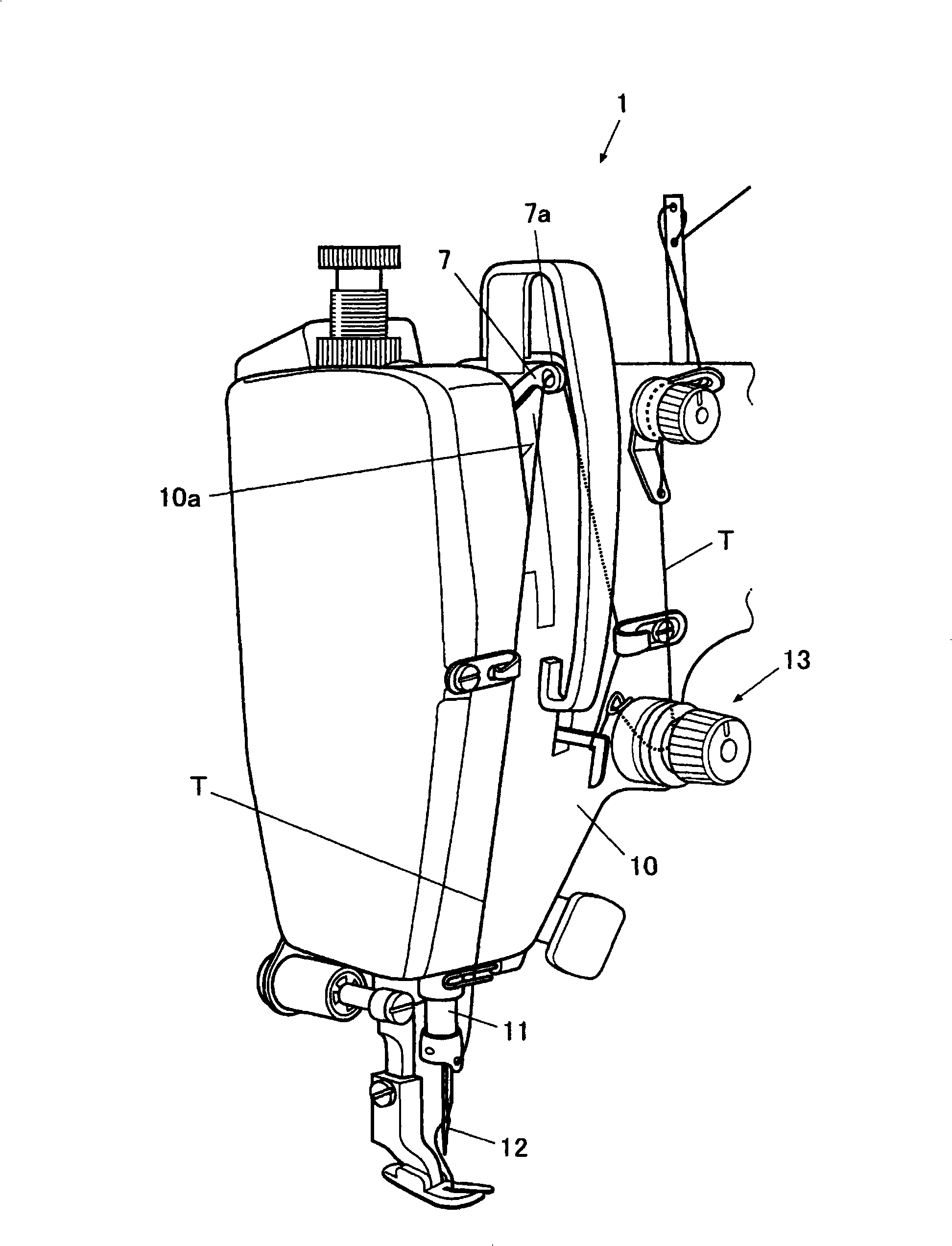
[0087]The needle bar 11 of the sewing machine 1 is supported on the sewing machine frame 102 so as to be movable up and down, and the sewing needle 12 is fixed at the lower end of the needle bar 11 . On the path of the needle thread (thread) T guided from the thread supply source (not shown) to the sewing needle 12, the thread adjusting device 13 is arranged on the front side of the sewing machine frame 10 (the side opposite to the operator). side), adjust the tension applied to the sewing thread T, and arrange the balance 7 along the vertical direction, which makes the thread hanging part 7a at the front end protrude from the balance groove 10a formed on the sewing machine frame 10.

[0088] The suture T is led out from a suture supply source such as a bobbin, hung on the suture adjustment device 13, and passed through the thread hanging portion 7a. Then, the suture T passed through the thread-hanging portion 7 a is guided toward the needle 12 and inserted into the...

Embodiment approach 2

[0125] In addition, as Embodiment 2, for example, as Figure 7 , Figure 8 As shown, a groove portion 42d is formed on the surface of the needle bar crankshaft 4 on the side of the needle bar crankshaft 5, which is opposite to the locus formed by the second convex portion 54a when the upper shaft 2 is rotated by driving the sewing machine motor (refer to Figure 8 The oblique line part), and the second convex part 54a is formed so that the front end part of the second convex part 54a is accommodated in the groove part 42d.

[0126] That is, since the needle bar crank rod 5 swings in the width direction by the rotation of the needle bar crank while moving up and down, the second convex portion 54a moves along a trajectory forming an arc. Therefore, a groove portion 42d is formed on the surface of the needle bar crankshaft 4 as well to follow the movement locus of the tip portion of the second convex portion 54 .

[0127] The groove portion 42d is formed to penetrate from the ...

Embodiment approach 3

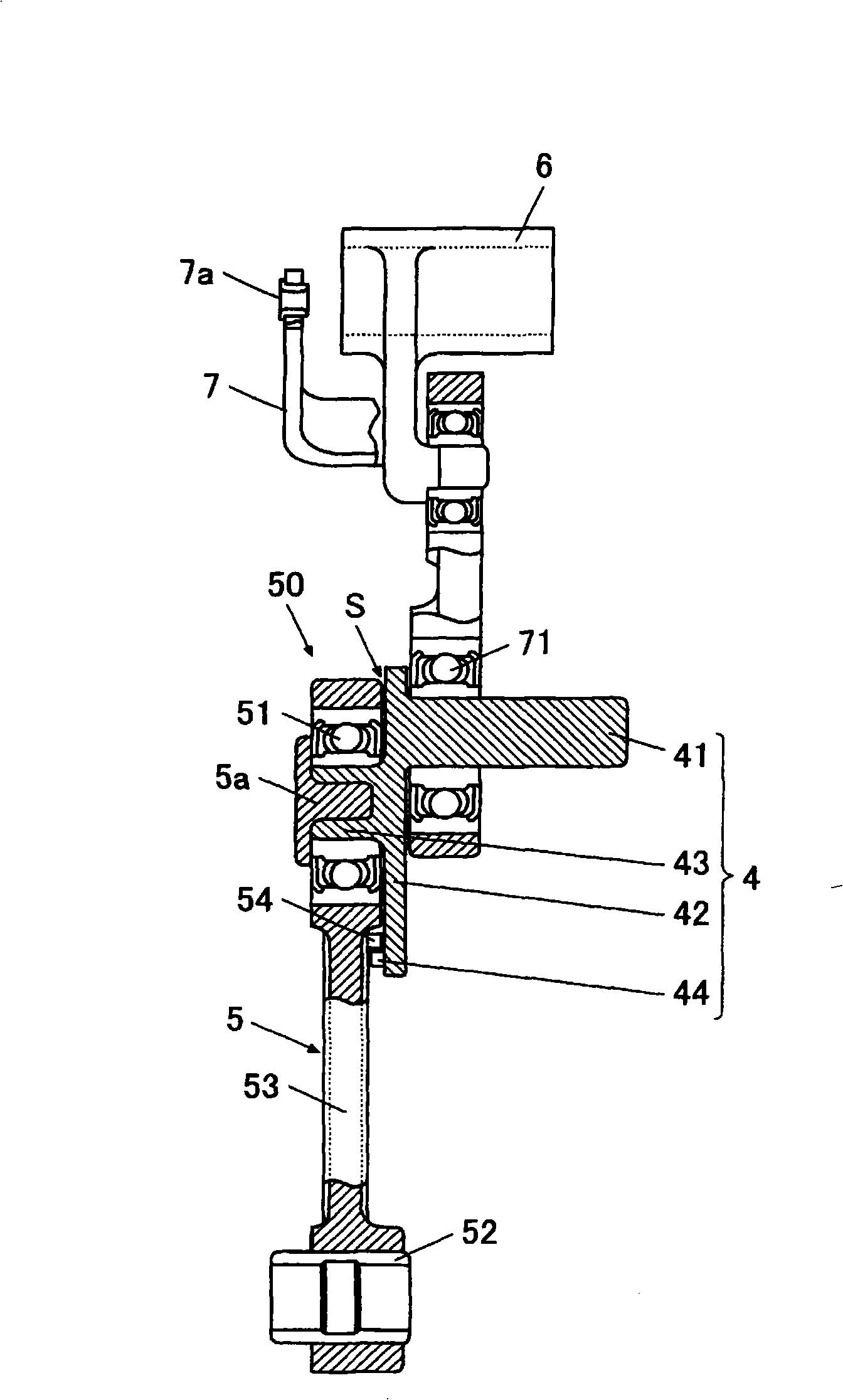
[0131] In addition, as Embodiment 3, for example, as Figure 9 As shown, at least a part of the outer periphery of the needle bar crankshaft 4 on the needle bar crank shaft 5 side is provided with a covering portion 42c that protrudes toward the ball bearing 51 and covers the gap V between the needle bar crankshaft 4 and the ball bearing 51 .

[0132] The covering portion 42 c is formed to extend outward from the outer circumference of the ball bearing 51 of the needle bar crank 5 . Accordingly, when the needle bar crank 4 rotates, the thread T is not wound around the ball bearing 51 but wound around the covering portion 42c.

[0133] In addition, the covering portion 42c may be provided over the entire outer circumference of the needle bar crankshaft 4, or may be formed at appropriate intervals so that the thread T does not enter the gap V. As shown in FIG.

[0134] In the case of employing the above configuration, the covering portion 42c covers the gap V between the needle...


PUM


Abstract

The invention provides a sewing machine preventing the suture curling to the needle bar crankshaft and the connection portion between the needle bar crankshafts and preventing the burning of the connection portion in advance. The sewing machine has an upper shaft, a balance weight, a needle bar crankshaft, a needle bar crankshaft bar, a libra crankshaft and a libra. The needle bar crankshaft has a first convex portion projecting to the side of needle bar crankshaft bar. The needle bar crankshaft bar has a second convex portion projecting to the side of the needle bar crankshaft. The front endportion of the second convex portion projects more to the side of the needle bar crankshaft compared with the front end portion of the first convex portion. The distance from the rotation center of the connection portion of the needle bar crankshaft bar and the needle bar crankshaft to the second convex portion is short than the distance between the rotation center and the first convex portion.

Description

technical field [0001] The present invention relates to a sewing machine having a balance that moves up and down in conjunction with an upper shaft to raise a needle thread. Background technique [0002] Currently, for example Figure 17 , Figure 18 As shown, the sewing machine 100 has: an upper shaft 101, which is connected with the sewing machine motor; a counterweight 102, which is fixed on the upper shaft 101; a needle bar crankshaft 103, which is fixed on the counterweight 102, located at the The eccentric position of the rotation center; and the needle bar crank shaft 106, one end of which is rotatably connected to the needle bar crank 103, and the other end is rotatably connected to the needle bar holding part 105 holding the needle bar 104, while the The sewing machine 100 has: a balance crankshaft 108 whose base end is rotatably supported on the sewing machine frame 107; It is rotatably connected to the front end of the balance crankshaft 108 . [0003] In addit...

Claims


Application Information

Patent Timeline
IPC IPC(8): D05B55/14D05B49/00
Inventor 山岸正则
Owner JUKI CORP
Why Eureka
Try Eureka