Differential confocal curvature radius measurement method and device

A differential confocal, radius of curvature technology, used in measuring devices, optical devices, instruments, etc., to achieve high stability, enhance fixed focus sensitivity, and reduce the effect of lens focal depth

Inactive Publication Date: 2009-09-09
BEIJING INSTITUTE OF TECHNOLOGYGY
View PDF1 Cites 40 Cited by
  • Summary
  • Abstract
  • Description
  • Claims
  • Application Information

AI Technical Summary

Problems solved by technology

[0007] The purpose of the present invention is to solve the problem of high-precision measurement of the radius of curvature of the lens, and propose a method and device for measuring the radius of curvature of the dif

Method used


Image

  • Differential confocal curvature radius measurement method and device
  • Differential confocal curvature radius measurement method and device
  • Differential confocal curvature radius measurement method and device

Examples


Embodiment 1

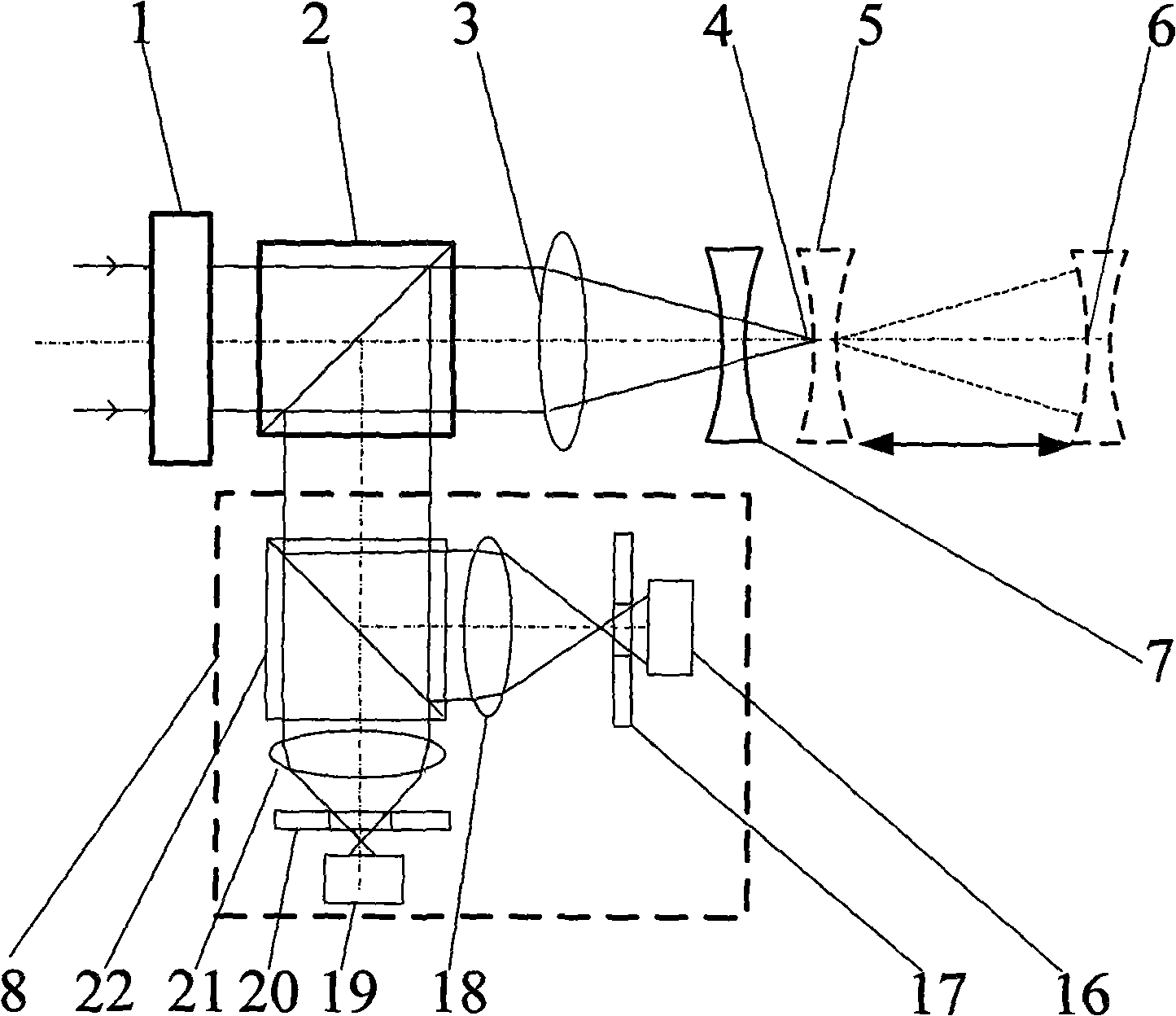
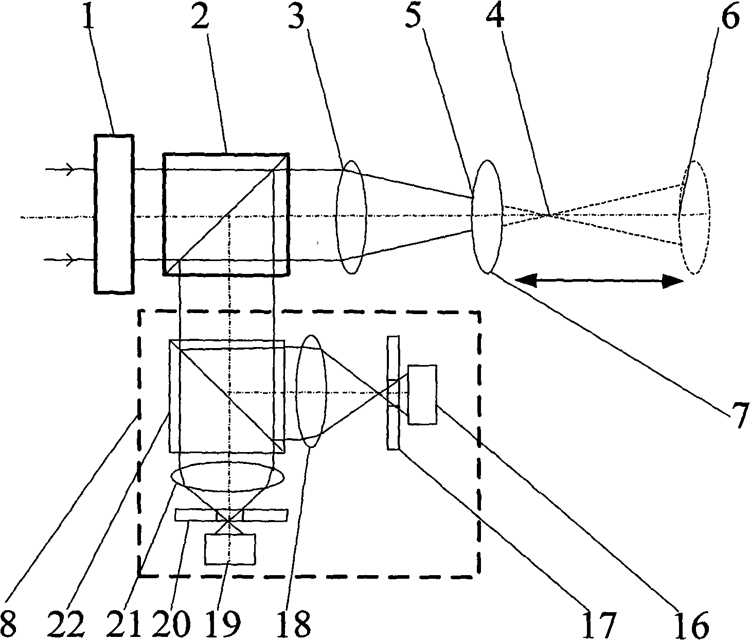
[0044] In this embodiment, differential confocal curvature radius measurement is performed on a concave lens. Such as Image 6 Shown is a differential confocal radius of curvature measurement method, the measurement steps are:

[0045] First, adjust the optical system before the measurement, turn on the light source 11, the emitted parallel light passes through the beam splitting system composed of the polarizing beam splitter 12 and the 1 / 4 wave plate 13, converges at the focal point 4 through the converging lens 3, and places the measured lens Near the focus position 4, after the light is reflected by the measured lens 7, it is reflected by the 1 / 4 wave plate 13 and the polarization beam splitter 12 and enters the beam splitter 22 of the differential confocal system; the beam splitter 22 divides the light into two paths, wherein One path of transmitted light passes through the lens 21 and the pinhole 20 to illuminate the photoelectric sensor 19, and the other path of reflec...

Embodiment 2

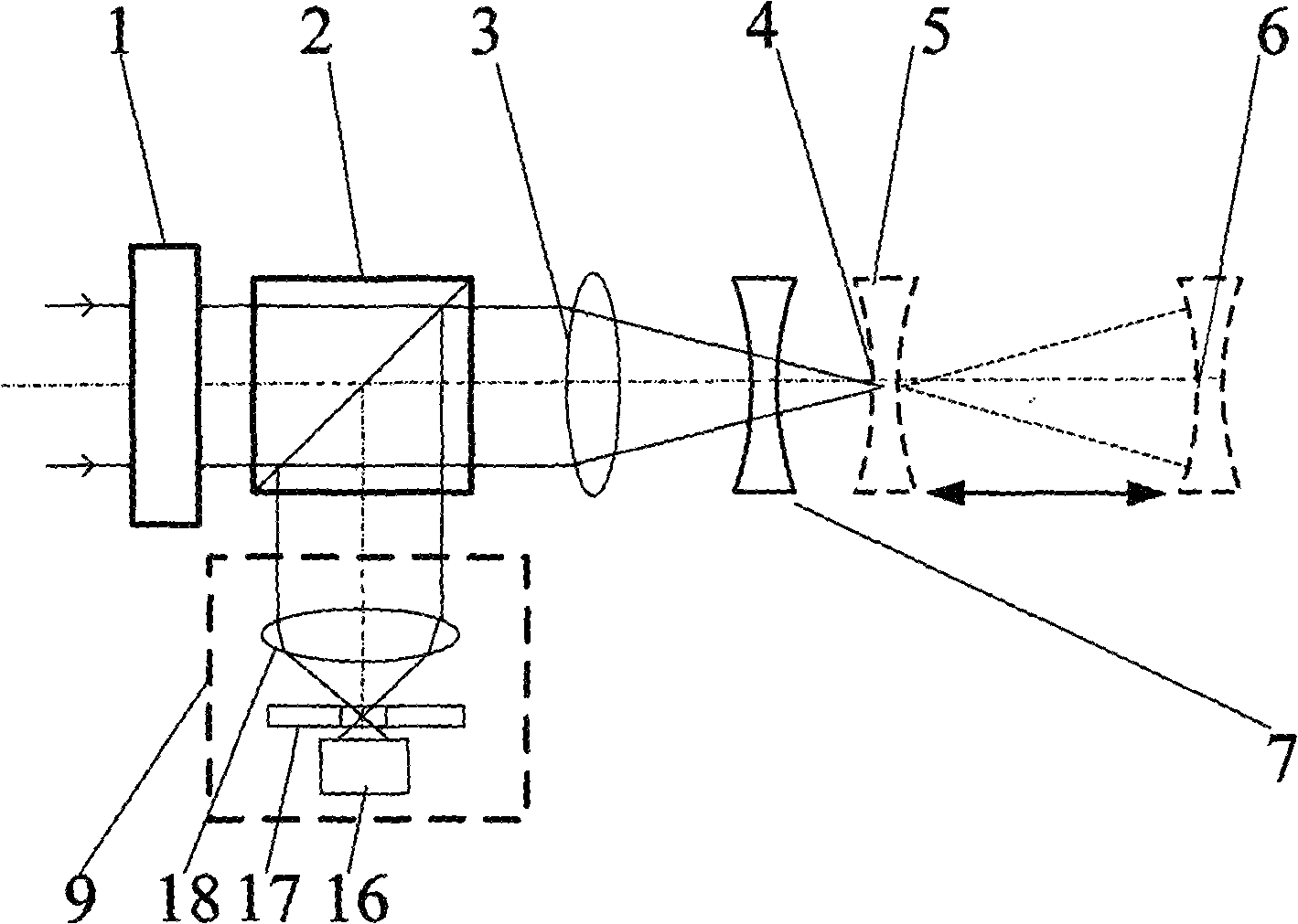
[0054] This embodiment is aimed at the measurement of the confocal curvature radius of the concave lens. According to the embodiment of the method for measuring the radius of curvature of the differential confocal, in the process of adjusting the optical path, the differential confocal system 8 in Embodiment 1 can be replaced by the confocal system 9, and the condenser lens 18 in the confocal system converges the light rays and converges them. The light passes through the pinhole 17 to illuminate the photoelectric sensor 16;

[0055] Such as Figure 7 As shown, in the measurement process, the lens under test 7 is scanned and moved along the translation stage 14 in the direction of the optical axis of the converging lens 3, and the confocal system determines the first point of the lens under test by detecting the maximum point of the corresponding signal of the photoelectric sensor 16. Focus position 5, responding to signals such as Figure 9 shown.

[0056] Then, the gratin...


PUM


Abstract

The invention belongs to the technical field of optical precision measurement and relates to a differential confocal lens curvature radius measurement method and a device. The method firstly utilizes the differential confocal focusing principle to respectively determine the positions of a top point and a spherical center of a measured lens and then measures the distance between the two focuses; meanwhile, the curvature radius measurement sensitivity can be improved by the pupil filtering technology during the measurement process. The invention firstly proposes to utilize the characteristic that a differential confocal response curve is corresponding to the top point and the spherical center of the measured lens when passing a zero point to realize the precise focusing, expands the application of differential confocal microscopy principle to the field of curvature radius measurement and forms the differential confocal focusing principle. The invention applies the differential confocal focusing principle and has the advantages of high measurement precision and strong anti-environmental interference ability, thereby being capable of being used in the detection of the lens curvature radius and the high-precision curvature radius measurement during the optical system assembly process.

Description

technical field [0001] The invention belongs to the technical field of optical precision measurement and can be used for lens curvature radius detection and high-precision curvature radius measurement in the optical system assembly process. technical background [0002] In the field of optics, the measurement of the radius of curvature of a lens plays an important role. It is very difficult to precisely measure the radius of curvature of an optical spherical surface on a high-quality spherical sample. The precise measurement of the radius of curvature of an optical spherical surface is an important link in the process of optical measurement and optical cold processing. As an important parameter of an optical lens, the high-precision measurement of its radius of curvature has always been a difficult point in the field of optical measurement. The main factor is that the contact measurement method requires the surface to be tested to be polished, which will bring about the mea...

Claims


Application Information

Patent Timeline
IPC IPC(8): G01B11/255
Inventor 赵维谦贾馨邱丽荣孙若端
Owner BEIJING INSTITUTE OF TECHNOLOGYGY
Why Eureka
Try Eureka