Bulge forming method and bulge forming apparatus

A technology of internal configuration and blank tube, which is applied in the field of extrusion forming and extrusion forming devices, can solve the problems of increased product deviation, difficult tube expansion forming, and reduced accuracy of tube expansion forming, and achieves the effect of simple structure and cost reduction

Inactive Publication Date: 2009-09-16
HONDA MOTOR CO LTD
View PDF1 Cites 13 Cited by
  • Summary
  • Abstract
  • Description
  • Claims
  • Application Information

AI Technical Summary

Problems solved by technology

[0013] However, since the hydraulic pressure of the pressurized liquid L must be repeatedly switched between high pressure and low pressure to expand and form the blank pipe 2, it takes time to switch the hydraulic pressure, making it difficult to perform high-speed pipe expansion.
In addition, since the pressurized liquid L cannot always be kept at a high pressure, the formability of the billet tube 2 to the mold 10 is lowered, and as a result, the accuracy of the tube expansion forming may be lowered, and the variation of the product may increase.

Method used


Image

  • Bulge forming method and bulge forming apparatus
  • Bulge forming method and bulge forming apparatus
  • Bulge forming method and bulge forming apparatus

Examples


no. 1 approach

[0046] (1) Structure of the first embodiment

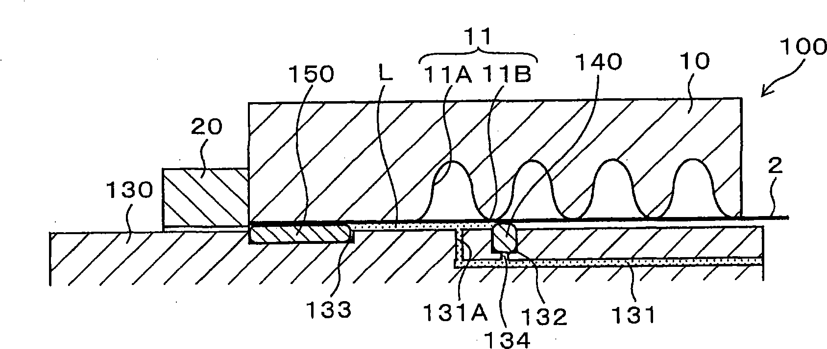
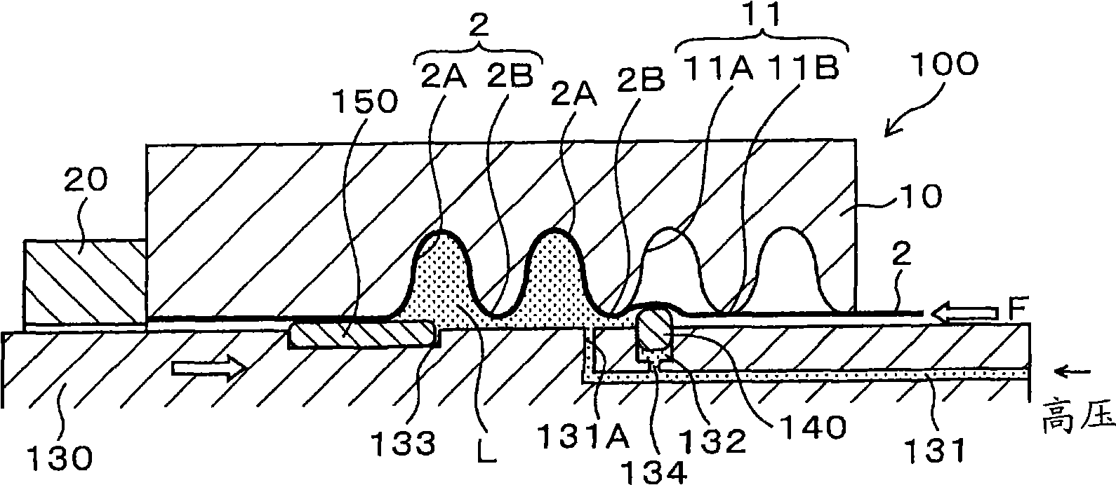
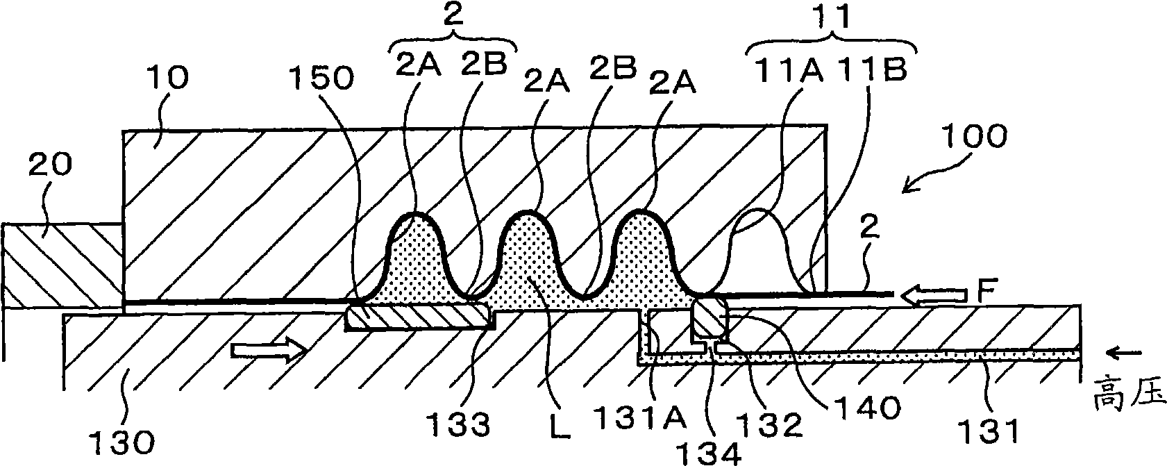
[0047] Next, a first embodiment of the present invention will be described with reference to the drawings. figure 1 It is a side sectional view showing a schematic structure of the extrusion molding apparatus 100 according to the first embodiment of the present invention. exist figure 1 The structure of the upper half of the extrusion forming device 100 is shown in . In addition, in this embodiment, for the Figure 7 The same components are denoted by the same symbols, and descriptions thereof are omitted.

[0048] A pressurized liquid supply channel 131 is formed inside the rod 130 , and the pressurized liquid L is supplied between the blank tube 2 and the rod 130 through the pressurized liquid supply port 131A therefrom. A pair of grooves 132, 133 are formed on the circumferential surface of the rod 130, and the pressure liquid supply port 131A is located between the pair of grooves. A pair of annular seal portions 140 , 1...

no. 2 approach

[0063] (1) Structure of the second embodiment

[0064] Next, a second embodiment of the present invention will be described with reference to the drawings. image 3 It is a side sectional view showing a schematic structure of the extrusion molding apparatus 200 according to the second embodiment of the present invention. Also, in the second embodiment, for the Figure 7 The same structural elements are marked with the same symbols, and their descriptions are omitted.

[0065]A rod 230 is arranged axially inside the blank tube 2 . The rod 230 is composed of a guide rod 235 fixed to the base tube 2 and a hollow rod 236 movably arranged around the guide rod 235 . The guide rod 235 has a large-diameter portion 235A and a small-diameter portion 235B smaller in diameter than the large-diameter portion 235A. The left end portion of the large-diameter portion 235A is fixed to the contact mold 20 . The small-diameter portion 235B is formed integrally with the right end portion of t...

no. 3 approach

[0079] Figure 5 A side sectional view showing a schematic structure of an extrusion molding device 300 according to a third embodiment of the present invention. In the third embodiment, the same reference numerals are assigned to the same components as those in the second embodiment, and descriptions of components having the same functions as those in the second embodiment are omitted. In the third embodiment, the pressure liquid supply port 231A is formed on the surface of the large-diameter portion 235A of the guide rod 235 instead of being formed on the surface of the small-diameter portion 235B of the guide rod 235 . Accordingly, the sealing portion 240 on the forming direction side at the start of forming the blank tube 2 can be brought into contact with the right end portion of the large diameter portion 235A. Therefore, the initial position of the sealing portion 240 on the side in the forming direction can be easily positioned at the start of forming the blank tube. ...


PUM


Abstract

The invention provides a bulge forming method and bulge forming apparatus. The sealing portion (140) is in an anterior side of a forming direction is applied with liquid pressure of the pressurized liquid (L) in a direction from the rod (130) toward the raw material tube (2) so as to be followable to bulging of the raw material tube (2), which enables at least a part of the sealing portion (140) in close contact with the raw material tube (2) permanently. The distance between the sealing portions (140,150) is set to have a length of at least two crest portions of the inner surface shape (11) of the die (10), and a length in the axial direction of the sealing portion (150) in a posterior side of the forming direction is set to have a length of at least one crest portion of the inner surface shape (11) of the die (10). And thus the sealing portion (150) can always in close contact with any of the vale sections (2B) formed by the flat section of the raw material tube (2) and the raw material tube.

Description

technical field [0001] The present invention relates to an extrusion forming method and an extrusion forming device as follows: that is, an axial compressive stress is applied to a blank tube arranged between a mold and a rod, and a pressurized liquid is supplied into the blank tube, and at the same time, the rod Movement in the axial direction so that the blank tube is shaped to the shape of the inner surface of the mould; especially the seal that seals the blank tube against the rod. Background technique [0002] The extrusion molding method is applied to the forming of containers and processing pipes, hollow structural parts of automobiles and various equipment, and the like. In the extrusion molding method, the pipe is formed into a desired shape by partially expanding the pipe so that the wall thickness of the pipe does not become thinner. The resulting bulging tubes include: flexible tubes that have a corrugated portion that has a plurality of expanded parts and are f...

Claims


Application Information

Patent Timeline
Patent Type & Authority Applications(China)
IPC IPC(8): B21D26/02B21D15/10B21D26/033B21D26/045
Inventor 小林卓生堀出
Owner HONDA MOTOR CO LTD
Why Eureka
Try Eureka