
Container with automatic switch valve

An automatic switch and valve technology, applied in the direction of soft tubular containers, containers, rigid containers, etc., can solve problems such as difficult to cooperate, difficult to comply with environmental protection, resource recovery, content leakage, etc., to save production procedures and costs, The effect of eliminating manual alignment assembly and reducing production costs

Active Publication Date: 2011-05-04
王南杰
View PDF0 Cites 3 Cited by
  • Summary
  • Abstract
  • Description
  • Claims
  • Application Information

AI Technical Summary

Problems solved by technology

[0009] 2. The above-mentioned valve is equipped with an elastic element on the sleeve to achieve the effect of automatically opening the valve, but the elastic element is made of metal, which is difficult to meet the requirements of environmental protection and resource recovery
[0017] 2. Since the above-mentioned container must manually control the switch of the liquid outlet, if the user forgets to close or put back the protective cover, the contents will leak and be lost
[0028] 2. They are all assembled by multiple components, which makes it difficult to cooperate well during the assembly process. If it is too loose, it will cause leakage, and if it is too tight, it will not be easy to squeeze out the contents.
[0029] 3. When used in cold climate areas, the content is not easy to be squeezed out due to the increase in viscosity. The user must increase the extrusion force, but the component may fall when the force is too large

Method used


Image

  • Container with automatic switch valve
  • Container with automatic switch valve
  • Container with automatic switch valve

Examples


Embodiment Construction

[0043] In order to disclose the technical scheme used in the present invention, the purpose of the invention and the effects achieved therein more completely and clearly, a more detailed description will be given below in conjunction with the accompanying drawings.

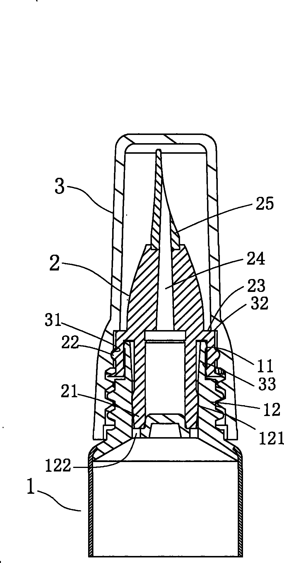
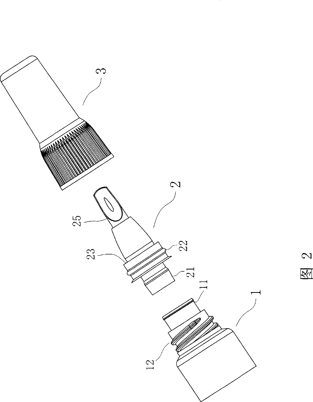
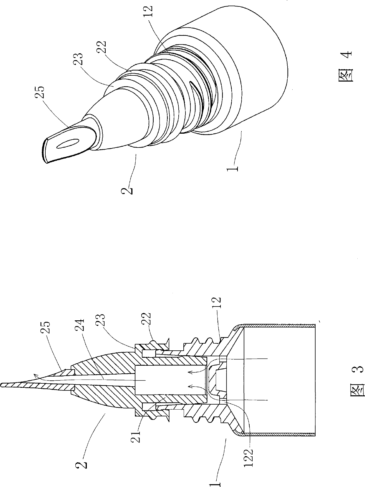
[0044] refer to figure 1 -4. The container with automatic switch valve includes a container body 1, an applicator 2 and a cover 3, wherein:

[0045] The inner wall of the head 12 of the container body 1 is directly formed into a valve seat 121, and several liquid outlets 122 are arranged horizontally at the bottom end of the valve seat 121 for the contents of the container body 1 to flow out. The thread is used to lock the cover body 3, and a card edge 11 is protruded at the top of the outer wall of the head 12, which can cooperate with the flange 33 on the mating surface of the applicator 2 to stop the application when the cover body 3 pulls the applicator 2 The device 2 is unlikely to be pulled out of the hea...


PUM


Abstract

A container with an automatic switch valve comprises a container body, a smearing tool and a cover body. A valve seat is directly formed at the inner wall of the head of the container body, and the bottom end of the valve seat is provided with a liquid outlet; the smearing tool is installed at the head of the container body, the top end of the smearing tool is connected with a brush, and the bottom end thereof is provided with a valve body which correspondingly opens or closes the liquid outlet arranged at the bottom end of the valve seat; the middle section at the outer wall of the smearing tool is provided with a trip, and the inner wall of the cover body is provided with a fastener for the embedment of the trip; and when the cover body is tightly locked at the head of the container body, the valve body arranged at the bottom end of the smearing tool is pressed down so as to close the liquid outlet of the valve seat, and when the cover body is opened, the fastener arranged at the inner wall is used for driving the valve body arranged at the bottom end of the smearing tool to open the liquid outlet of the valve seat. In the container, the valve is closed when the cover body is screwed tightly, thus preventing contents from leaking out; and the valve is opened when the cover body is opened, thus extruding out proper amount of the contents to be directly smeared, with simple and convenient use. The container with the automatic switch valve has simple structure, and convenient and quick assembly, and can greatly reduce the production cost.

Description

technical field [0001] The invention relates to a container capable of automatically opening and closing valves, in particular to a valve seat that is directly formed on the inner wall of the container body, and the valve body of the applicator is driven by the locking and opening of the cover body, so that the contents of the container body The outflow can be automatically opened or closed with the function of automatic switch valve container. Background technique [0002] The container that can squeeze out the content is usually used to hold ointment and cream cosmetics, etc., and the liquid outlet of the container is equipped with a smearing device. After squeezing out an appropriate amount of content during use, it can be directly applied without sticking hands. Cooperating with applicator brushes of various shapes, the user can apply comfortably and use it conveniently. If the container closes the lid without a valve to close the liquid outlet of the container, when th...

Claims


Application Information

Patent Timeline
Patent Type & Authority Patents(China)
IPC IPC(8): B65D25/38B65D35/36B65D47/20B65D41/02B65D35/44
Inventor 王南杰
Owner 王南杰
Learn More