High-strength electric power-transmitting iron tower

A transmission tower, high-strength technology, applied in the field of transmission towers, can solve the problems of increasing the strength and economy of the whole tower, and achieve the effect of good strength

Inactive Publication Date: 2009-09-16
刘华友
View PDF1 Cites 2 Cited by
  • Summary
  • Abstract
  • Description
  • Claims
  • Application Information

AI Technical Summary

Problems solved by technology

[0005] In order to solve the problem that existing power transmission towers have contradictions between increasing the strength of the whole tower and economical efficiency, the present invention provides a high-strength power transmission tower, which can solve the problems existing in the use of existing power transmission towers. There is a contradiction between increasing the strength of the whole tower and economy

Method used


Image

  • High-strength electric power-transmitting iron tower
  • High-strength electric power-transmitting iron tower

Examples


Embodiment Construction

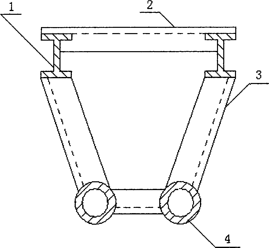
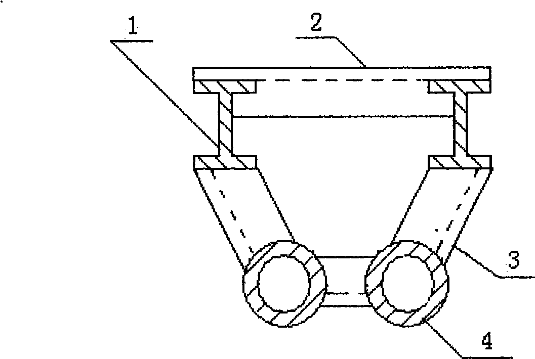
[0021] The structural details and specific implementation methods of the high-strength power transmission tower of the present invention will be described below in conjunction with the accompanying drawings.

[0022] Such as figure 1 As shown, the I-shaped steel (1), the cross brace (2), the diagonal brace (3) and the steel pipe (4) are welded to form the trapezoidal section tower body of the transmission tower, and the trapezoidal lower bottom column of the tower body is made of I-shaped steel (1) make, and the upper base column of tower body cross-section trapezoid is made with steel pipe (4), and the cross strut (2), diagonal strut (3) of tower body are made with angle steel. The direction of the maximum bending capacity of the I-beam (1) at the column part of the tower body is the same as the direction of the height of the trapezoidal section of the tower body. An appropriate amount of diagonal stays can be arranged in the vertical direction and the horizontal direction ...


PUM


Abstract

The components of existing electric power-transmitting iron tower are mostly angle steel with poor anti-bending strength and have the disadvantage of contradiction between entire tower strength improvement and economical efficiency. The technical proposal adopted for solving the disadvantage is as follows: the tower body horizontal section structure and the tower head crossarm vertical section structure of the electric power-transmitting iron tower are both designed into trapezoid; the lower bottom edge of the tower body section trapezoid faces away from the maximum forced direction of the electric power-transmitting iron tower; the lower bottom edge of the tower head crossarm section trapezoid face upwards; both an upright post at the lower bottom edge of the tower body section trapezoid and a crossbeam at the lower bottom edge of the tower head crossarm trapezoid are made of I-beam or channel-section steel, and both an upright post at the upper bottom edge of the tower body section trapezoid and a crossbeam at the upper bottom edge of the tower head crossarm trapezoid are made of steel tubes. The anti-bending section modulus of the I-beam is higher than that of the angle iron by about one time, therefore, the manufacturing of main forced components of the electric power-transmitting iron tower by adopting the I-beam or the channel-section steel to replace the angle steel is reasonable from the point of view of mechanics and is economical from the point of view of economy.

Description

technical field [0001] The invention relates to power transmission equipment, especially power transmission iron towers. Background technique [0002] Most of the components of the existing transmission towers are angle steels. We know that the bending resistance of angle steels is poor, and then the angle steels are combined to form a regular quadrilateral tower body, which makes the angle steels placed on the section where the mechanical properties are not good It is even more unreasonable to use it in the -x direction. In order to improve the strength of the transmission tower, the column of the tower body is changed to a steel pipe, such as the "Transmission Tower" with the patent application No. 99112190.2, which has such a structure. % or so, the strength of the transmission tower can be improved like this, but the degree of improvement is still unsatisfactory. [0003] In order to improve the anti-ice and snow freezing ability of the power cable, it is necessary to ...

Claims


Application Information

Patent Timeline
IPC IPC(8): E04H12/00E04H12/24
Inventor 刘华友
Owner 刘华友
Why Eureka
Try Eureka