Microflow distribution device, manufacturing method and application thereof

A dispensing device and microfluidic technology, used in chemical instruments and methods, optomechanical equipment, testing pharmaceutical preparations, etc., can solve the problems of expensive equipment and complicated operation methods.

Inactive Publication Date: 2009-09-16
PEKING UNIV
View PDF0 Cites 39 Cited by
  • Summary
  • Abstract
  • Description
  • Claims
  • Application Information

AI Technical Summary

Problems solved by technology

[0004] Although these techniques significantly reduce the reaction volume and increase the reaction scale, they generally only work in closed reaction spaces such as polydimethylsiloxane (PDMS) microchambers or liquid plugs, and at the same time, they still exist Disadvantages such as expensive equipment and complicated operation methods

Method used


Image

  • Microflow distribution device, manufacturing method and application thereof
  • Microflow distribution device, manufacturing method and application thereof
  • Microflow distribution device, manufacturing method and application thereof

Examples


Embodiment 1

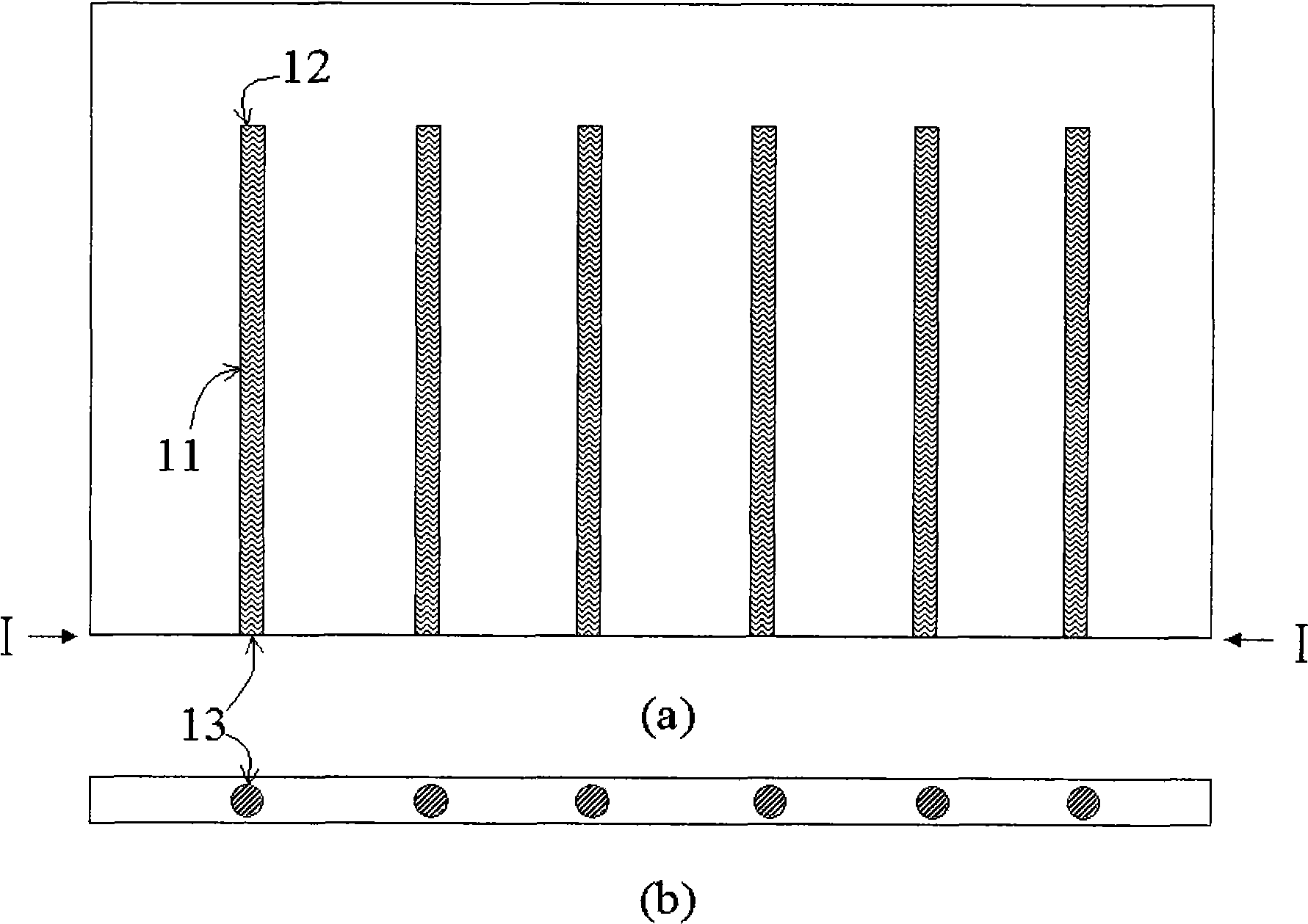
[0062] The following will refer to the attached figure 1 The structure of the microfluidic distribution chip with multiple parallel microfluidic channels is described in detail. figure 1 (a) Front view of the microfluidic distribution chip, figure 1 (b) is a cross-sectional view along the I-I direction, 11 is the microfluidic channel, 12 is the inlet of the microfluidic channel, and 13 is the outlet of the microfluidic channel.

Embodiment 2

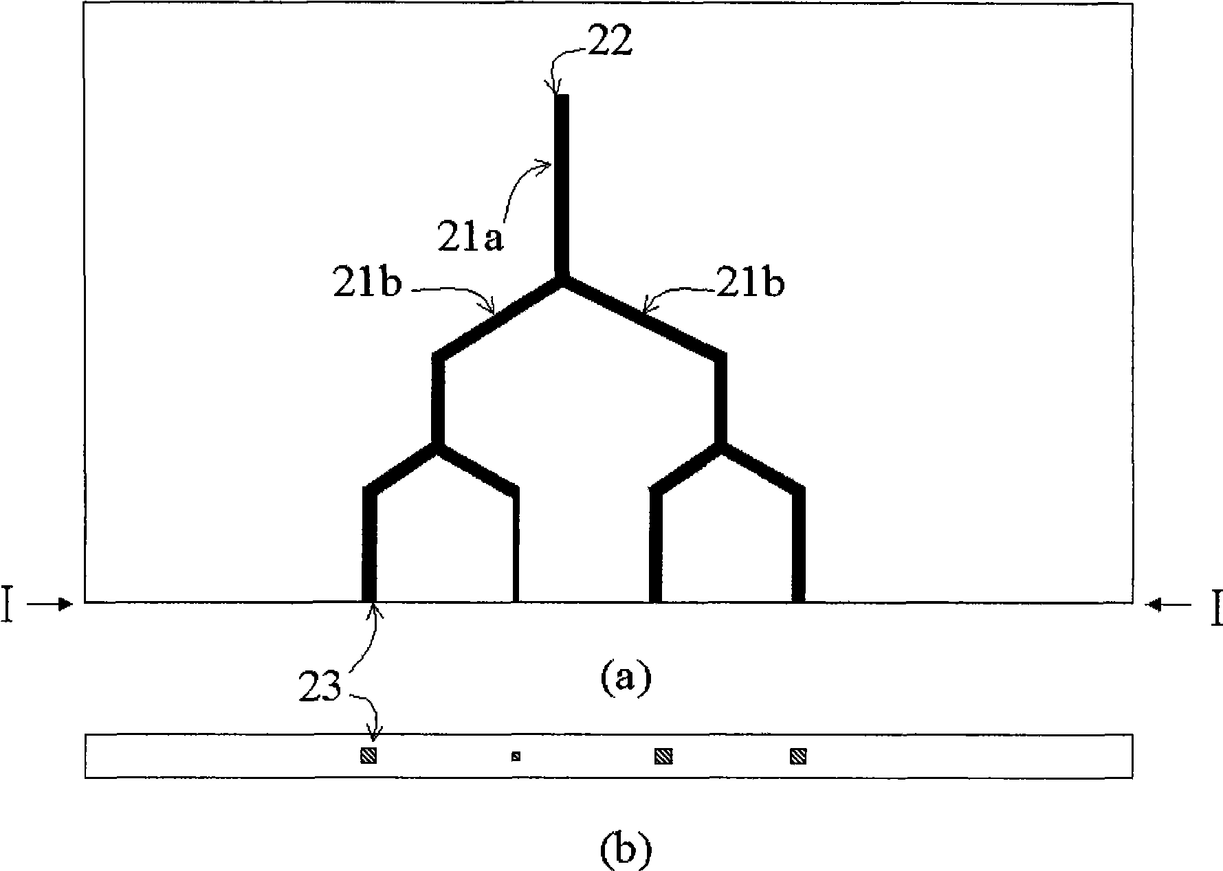
[0064] The following will refer to the attached figure 2 The structure of a microfluidic distributing chip with a group of microfluidic channel trees formed by a root microfluidic channel branching multiple times is described in detail. figure 2 (a) Front view of the microfluidic distribution chip, figure 2 (b) is a cross-sectional view along the I-I direction, 21a is the root microfluidic channel, 21b is a new microfluidic channel formed by the root microfluidic channel through a bifurcation, 22 is the entrance of the microfluidic channel, and 23 is the microfluidic channel outlet of the flow channel. Two new microfluidic channels 21b formed by bifurcating the root microfluidic channel together with the root microfluidic channel 21a form a Y shape.

Embodiment 3

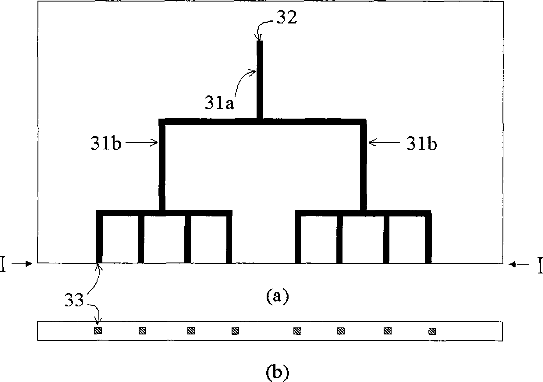
[0066] The following will refer to the attached image 3 The structure of another microfluidic distribution chip with a group of microfluidic channel trees is described in detail. image 3 (a) Front view of the microfluidic distribution chip, image 3 (b) is a cross-sectional view along the I-I direction, 31a is the root microfluidic channel, 31b is a new microfluidic channel formed by the root microfluidic channel through a bifurcation, 32 is the entrance of the microfluidic channel, and 33 is the microfluidic channel outlet of the flow channel. Two new microfluidic channels 31b formed by bifurcating the root microfluidic channel together with the root microfluidic channel 31a form a letter T shape.


PUM

PropertyMeasurementUnit
angleaaaaaaaaaa

Abstract

The invention relates to a microflow distribution device, a manufacturing method and an application thereof, belonging to the field of minim testing device, or rather the field of microflow distribution. The microflow distribution device of the invention comprises a microflow distribution chip which is provided with at least one microflow layer; each microflow layer is provided with at least two paratactic microfluidic channels or a group of microfluidic channel trees formed in the way that a root microfluidic channel branches off for at least once; the microfluidic channel covers a cross-sectional area of at least 1 Mum <2>-1mm <2>; the entrance and exit are connected with the outside while all the other parts are arranged inside the microflow distribution chip. The microflow distribution device of the invention features low price and easy manufacturing, exact distribution of liquid samples at nano liter level and wide application prospect in multiple fields such as microfluid, microanalysis, drug screening, cell detecting and combined chemical reaction.

Description

technical field [0001] The invention relates to the field of micro-test equipment, and precisely belongs to the field of micro-fluid distribution. Background technique [0002] Most biochemical reactions and cell-based chemical assays, especially large-scale screening assays and life science research at the single-cell level, are performed in liquid phases in nanoliter to microliter volumes. The small-volume reaction not only reduces the cost of a single reaction, but also increases the concentration of reagents for efficient reaction, while greatly reducing the waste of reagents. These assays are often very demanding, requiring extensive pipetting to transfer liquid samples. Now, accurate small-volume liquid sample dispensers at the microliter level have been commercialized, but how to further expand to the nanoliter level is still one of the main challenges faced by large-scale reactions. On the other hand, some other methods, such as non-contact printing and ultrasonic ...

Claims


Application Information

Patent Timeline
Patent Type & Authority Applications(China)
IPC IPC(8): G01N33/48G01N33/15G03F7/00
CPCB01L3/0203B01L2300/0864B01L2300/0829B01L2200/021B01L2200/0642B01L3/502715
Inventor 黄岩谊席建忠王建斌周莹
Owner PEKING UNIV
Why Eureka
Try Eureka